5 setting write-protect feature, Las capability, Write-protect feature – Flowserve 400MD Logix User Manual
Page 26
LAS Capability
The Logix 3400MD digital positioner is capable of operating as the Link Active Scheduler (LAS). The LAS is a fieldbus device which controls traffic on the
network, such as controlling token-rotation and coordinating data publishing. This fieldbus function is active in only one device at any given time on a net-
work. Devices which can be designated as the LAS may be an operator station or a field device.
The Logix 3400MD digital positioner can be designated as a LAS so that, in the event of a failure of the primary LAS, control in the field could continue.
Please note that the Logix 3400MD digital positioner is not designed to be the primary LAS, and, therefore, the LAS capability in the positioner
is regarded as a backup LAS. In some remote applica tions where there is no host computer continuously connected this device may be con-
figured as the primary LAS.
The LAS may be disabled by defining the Logix 3400MD as a Basic device in the host system or performing a factory default reset. Factory default resets the
positioner to a basic device
6.5 Setting Write-Protect Feature
Write-protect Feature
The Logix 3400MD digital positioner is available with a write protect feature. It consists of a dip switch located on the device’s electronics
board that can be set to enable read only access (write-protect) to the device’s configuration. When the dip switch is in the “On” position and
the corresponding device parameter is set, the device’s configuration parameters and calibration data can only be read or viewed, (device
configuration is write protected).
ATTENTION:
The dip switch is factory set for read- and write-access (not write-protected) “Off” position. (If the dip switch is in the
“On” position, the positioner must be powered down before changing the dip switch.)
NOTE: The write protect dip switch is used in conjunction with the FEATURE_SEL parameter and is explained below.
Refer to the following steps to set the write protect dip switch.
1. Remove power to Logix 3400MD.
2. Loosen cap lock and unscrew the main housing cover of housing.
3.
ATTENTION: Using a ground strap or ionizer is highly recommended when handling the electronics module because electrostatic
discharges can damage certain circuit components.
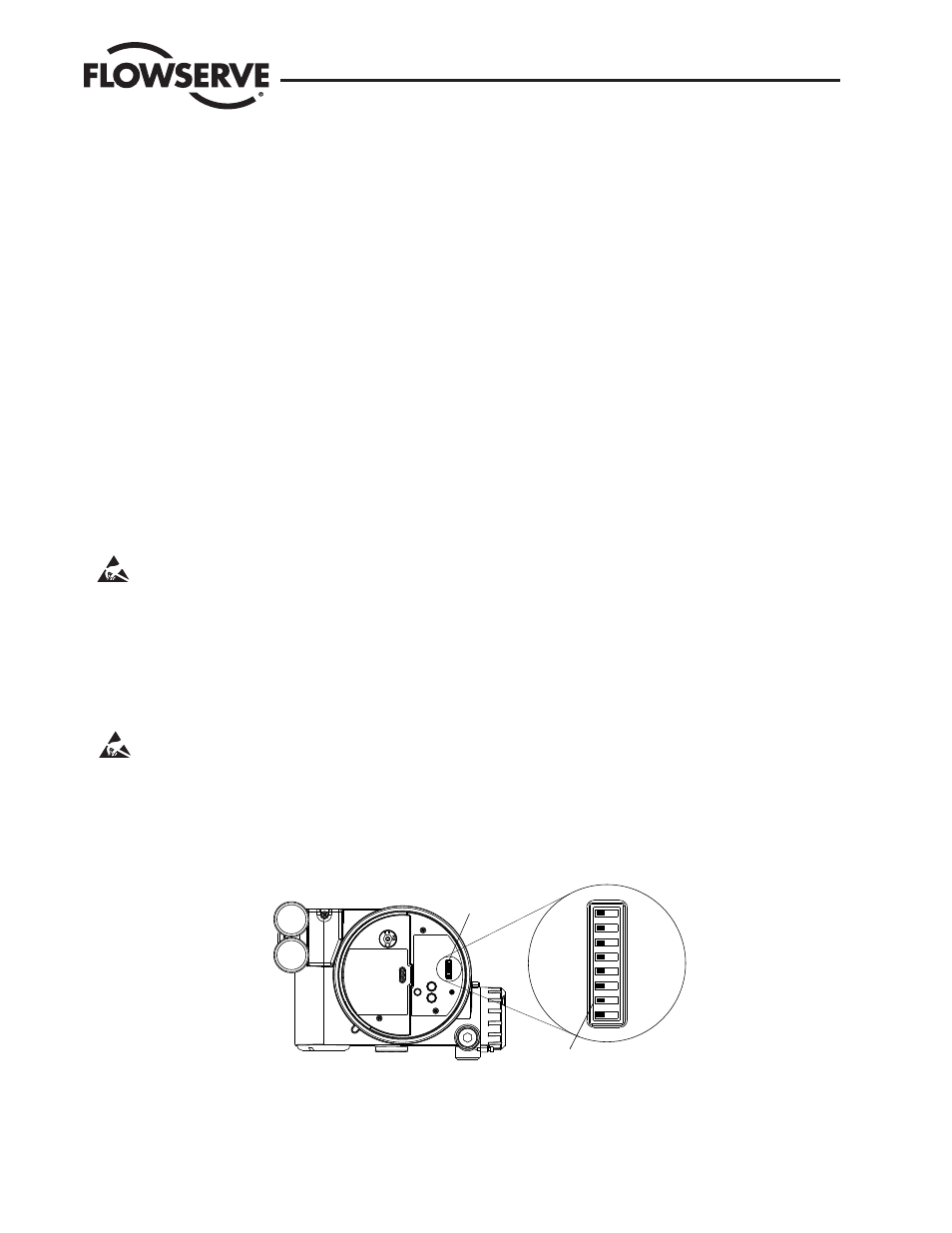
4. Locate the dip switch on the main electronics boards in the housing.
5. Set write-protect dip switch to the appropriate position on the electronics board. See Figure 6.1 and Table 6.1.
6. Replace the cover and lock the locking screw
Figure 6.1 Write-protect DIP Switch Location on Main PCB Cover
DIP Switch Block
FF Write Protect
Dip Switch
Off
On
Logix 3400MD Digital Positioner LGENIM3405-02 11/13
26