Transducer position source selection, Ao block mode, Troubleshooting guide – Flowserve 400MD Logix User Manual
Page 89
1. Set ENABLE_DISABLE to ACTIVE and write the parameter.
2. Set SIMULATE_VALUE and SIMULATE_STATUS as desired and write the parameter.
3. Read the READBACK parameter. This should reflect the value and status which was set in the SIMULATE parameter.
NOTE: The TRANSDUCER_VALUE and TRANSDUCER_STATUS will continue to be updated by the transducer source as described in the next
section.
Transducer Position Source Selection
The source of the TRANSDUCER_VALUE and TRANSDUCER_STATUS in the SIMULATE param
eter is determined by the FEATURE_SEL parameter in the Resource Block. If FEATURE_SEL OUT_READBACK not selected (default) then the
transducer source will be the AO OUT parameter. If FEATURE_SEL OUT_READBACK is selected then the transducer source will be the FINAL_
POSITION_ VALUE from the Transducer Block.
Because the FINAL_POSITION_VALUE in Logix 3400MD transducer block reflects the actual actuator position, the OUT_READBACK feature
should be always be selected during normal operation.
AO Block Mode
To connect the AO block input to the output, the AO block must be in AUTO mode.
10.9 Logix 3400MD Digital Positioner
Troubleshooting Guide
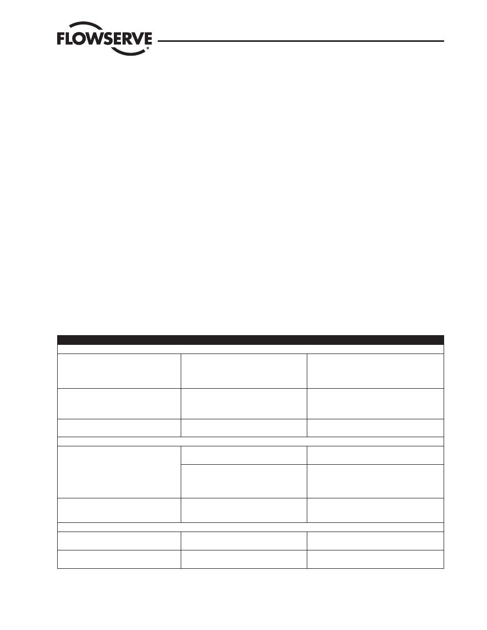
Table 10.12 Symptom Chart
Failure or Problem
Probable Cause(s)
Refer to Section(s)
Mounting and Installation
LED won’t blink
1. Input voltage not correct
1. See Electrical Wiring Summary in
Sec-
tion 5.
2. Termination may be incorrect.
3. Calibration is in process.
Valve moves in wrong direction with no change
in input signal
1. May be tubed for wrong air action.
2. Spool stuck.
1. See Air Action in Section 6.
2. See Spool Valve instructions in Logix 3400MD
Digital Positioner IOM.
Unit does not respond to fieldbus command.
1. Unit is not configured correctly.
1. See Theory of Operation on page 3.
2. Error occurred during calibration.
2. See Calibration in Section 9.
Calibration
LEDs blink RGGY after a Re-Cal operation. Valve
stays in fully open or closed position.
1. Configured for linear on a rotary mounting.
1. See Re-Cal button Section 9.
2. Feedback linkage out of range.
1. Valve didn’t fully stroke during calibration (low
or no air supply).
1. See Re-Cal button Section 9.
2. Stuck Spool.
2. See Spool Valve instruction in Logix 3400MD Digi-
tal Positioner IOM.
On a rotary, valve has a dead band at the fully
open or closed position.
1. Mechanical travel is not centered within the
electrical measurement range (position sensor
out of range).
1. See Linear vs. Rotary in Section 6.
Control and Tuning
Valve won’t saturate at closed position.
1. May need to enable MPC
1. See MPC in Section 8.
2. Calibration required.
Valve won’t go below or above a certain limit.
1. Soft limits are not enabled
1. See Advanced Features in Section 10.
2. MPC is not enabled
Logix 3400MD Digital Positioner LGENIM3405-02 11/13
89