10 internal positioner issues, Positioner inner loop control and tuning – Flowserve 400MD Logix User Manual
Page 90
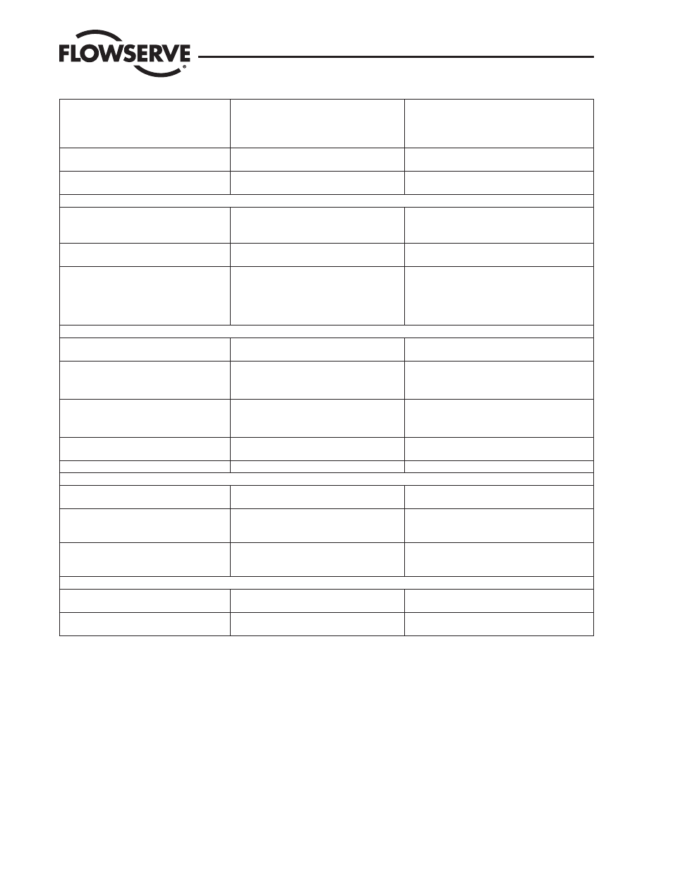
Sticking or hunting operation of the positioner.
1. Contamination of spool valve assembly
1. See Air Supply Requirements on page 15. See
Spool Valve in Section 10.
2. P+I setting incorrect
2. See Setting P+I Parameters in Section 10.
3. Excessive Stiction
3. Enable Hi Friction Feature
Large initial deviation; only present on initial
power-up.
1. Inner loop offset not correct.
1. See Setting P+I Parameters in Section 10.
Stem position movement is not linear with com-
mand.
1. Custom characterization is enabled
1. See Custom Characterization in Section 10.
Fieldbus Communication
Logix 3400MD digital positioner will not com-
municate with fieldbus.
1. Power problem.
1. See Wiring the Logix 3400MD Digital Positioner to
a Fieldbus Network on page 19.
2. FB card connection.
2. Verify FB protocol being used.
Configurator displays ‘Unknown’ after it con-
nects.
1. DD has not been loaded in the configurator
correctly.
1. Reload DD making sure Valtek products are listed.
Erratic communications occur.
1. Maximum cable length or impedance exceed-
ed
1. See Wiring the Logix 3400MD Digital Positioner to
a Fieldbus Network on page 19.
2. Card not receiving enough power. (Laptop bat-
teries possibly low)
2. Refer to AGA-181 for Network checkout proce-
dure.
3. Interference with I.S. barrier
Alarms
Temperature alarm occurs.
1. Ambient temperature has exceeded electronics
ratings
1. See Temperature Alarm in Section 8.
Hall sensor alarm occurs.
1. Hall connector may have bad connection
1. See Hall sensor Alarm in Section 8.
2. Sensor may be damaged
3. Low air supply pressure
3. Check air supply
Modulator current alarm occurs.
1. Modulator minimum pressure may be too low. 1. See Modulator current Alarm in Section 8.
2. Clogged orifice
3. Bad cable connection
EEPROM checksum alarm occurs.
1. Error when reading non-volatile memory stor-
age
1. See EEPROM checksum Alarm in Section 8.
Multiple internal flags occur.
1. Bad micro-controller on main PCB assembly.
LEDs
LED four blink sequence begins with green
1. Any sequence beginning with a green light is a
normal operating mode .
1. Go to Section 7.9 in the Logix 3400MD IOM
LED four blink sequence begins with yellow
1. Any sequence starting with a yellow light indi-
cates that the unit is in a special calibration or test
mode, or that there was a calibration problem.
1. Go to Section 7.9 in the Logix 3400MD IOM
LED four blink sequence begins with red
1. Any sequence starting with a red light indi-
cates that there is an operational problem with
the unit
1. Go to Section 7.9 in the Logix 3400MD IOM
Advanced Features
Will not display pressure readings.
1. Is configuration set to advanced?
1. See Standard vs. Advanced Diagnostics in Sec-
tion 10.
MPC will not function.
1. Is lower soft limit >= 0%. 2. Set-point should
be 1 percent hysteresis around MPC.
1. See MPC in Section 8.
10.10 Internal Positioner Issues
Positioner Inner loop Control and Tuning
Setting P+I Parameters: Using the configurator, the user can set individual tuning parameters. To use the Auto Tune feature of the Logix
3400MD refer to section 7.4 in the Logix 3400MD IOM. A few key points are mentioned below.
GAIN_UPPER, GAIN_LOWER and GAIN_MULT: These three parameters are related by the following formula.
Proportional gain = maximum gain - | deviation | x gain multiplier
If proportional gain < minimum gain, then proportional gain = minimum gain
Logix 3400MD Digital Positioner LGENIM3405-02 11/13
90