4 master station ii – Flowserve MX-100 Field Unit User Manual
Page 11
11
MX/DDC-100 Field Unit Installation and Maintenance FCD LMENIM2329-00 – 2/08
flowserve.com
2.2.4 Master Station II
A Master Station II may be used in the DDC-100 system. Master Station II’s are normally located in the control room,
and serve as the interface between the field units and the host controller. The following functions are provided:
Continuous polling of actuator network
•
Message routing to/from field units
•
Data concentration
•
Data logging
•
In this configuration, the Master Station II receives commands from a host controller. The Master Station II communi-
cates with the host controller using the Modbus Protocol and the RS-232 or RS-485 electrical standard. See Bulletin
FCD LMENIM5001, DDC-100 Master Station II Installation and Operation Manual for details.
The Master Station II sends commands and messages to, and gathers responses from, the field units. The
commands and messages are sent via RS-485 data signals. The gathered responses are stored in a poll table in the
Master Station II and are periodically updated by sequential polling of the field units. The Master Station II controls up
to 250 field units. See Section 3.1.2.3, Network Cable Connection to Host System or Master Station II.
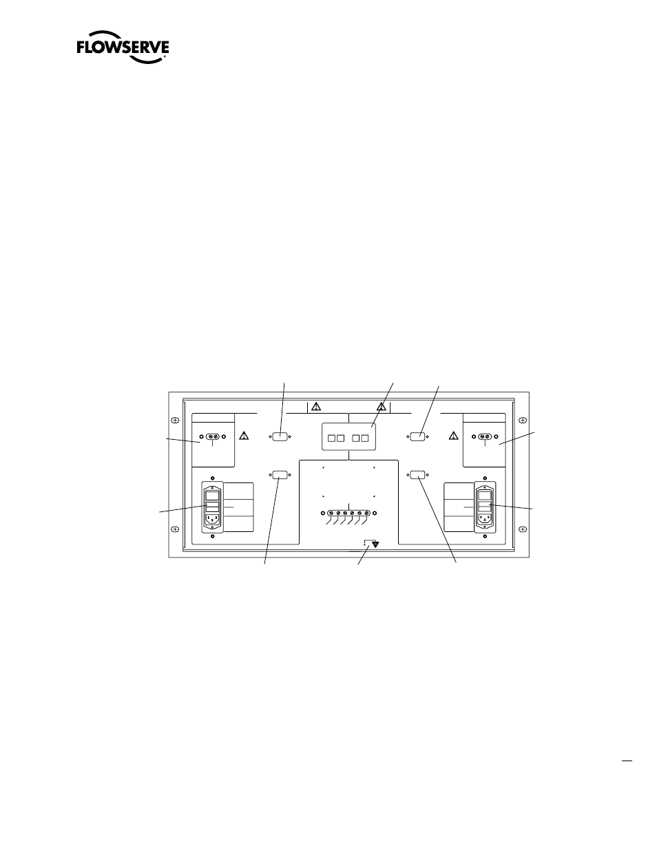
Figure 2.4 – Typical Master Station II (rear view)
1. Ethernet ports
2. Printer/Debug port
3. DCS port
4. Auxiliary 24 VDC power connection
5. Main power switch and connector for 120-240 VAC
6. Electrostatic ground
7. Hot Standby unit main power switch and connector for 120-240 VAC
8. Hot Standby auxiliary 24 VDC power connection
9. Hot Standby DCS Port
10. Hot Standby Printer/Debug Port
o
l
FUSES
FUSES
l
o
ETHERNET
DO NOT USE
SINGLE
--
+
24VDC
PROPER OPERATION
INSIDE OF UNIT FOR
INPUT ONLY
EXTERNAL 24VDC
MOVE JUMPERS ON
250 V
INPUT
POWER
~1.5A
100-240VAC
ON
OFF
FUSES
2 AMP
DCS
DA
TA * GND
CHANNEL B
PRINTER / DEBUG
WITH 110-240VAC
OPTIONAL
DO NOT USE
HOT STANDBY
GND
DA
TA
*
DA
TA
DCS
PRINTER / DEBUG
ON
OFF
~1.5A
INPUT
100-240VAC
250 V
POWER
2 AMP
FUSES
--
+
24VDC
PROPER OPERATION
INSIDE OF UNIT FOR
INPUT ONLY
EXTERNAL 24VDC
MOVE JUMPERS ON
WITH 110-240VAC
CHANNEL A
DA
TA
NO SERVICEABLE PARTS INSIDE
1
2
3
5
4
6
9
7
8
10