Host, Network controller) – Flowserve MX-100 Field Unit User Manual
Page 36
MX/DDC-100 Field Unit Installation and Maintenance FCD LMENIM2329-01 – 03/11
36
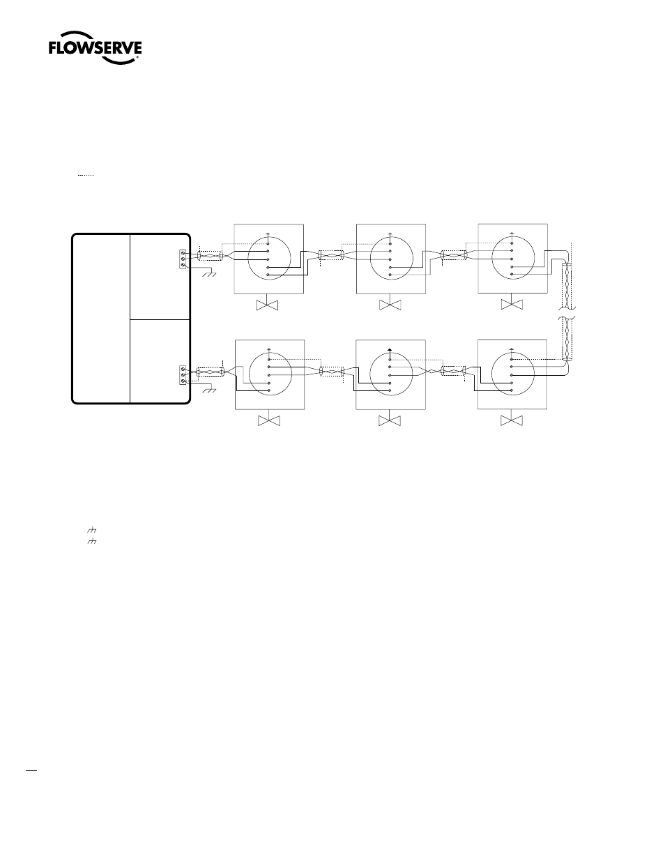
Figure 3.8 – Redundant bi-directional loop topology
Daisy Chain
The daisy chain topology is identical to the redundant loop topology with the following exception: only one end of the
network is connected to the host device.
The daisy chain topology is wired as follows:
1. Connect the host port 1 to the first field unit port A1 at MX terminal block numbers 4 and 5.
2. Connect port A2 of this field unit at MX terminal block numbers 14 and 13 to port A1 of the next field unit.
3. Continue steps 1 and 2 until the last field unit is connected.
NOTE: If a stub cable is run from port A2 of the last field unit (MX terminal block numbers 14 and 13) to a planned
field unit location, or the last field unit is disconnected, the open end of the cable must be terminated with a 120 ohm
resistor to prevent unacceptable signal reflections. Termination impedance is supplied when the actuator field unit is
the last unit.
The daisy chain topology utilizes the field unit repeater circuitry, and therefore supports the same number of field
units and distances as the redundant bi-directional loop topology. However, the daisy chain topology is less reliable
than the redundant bi-directional loop topology because the host can only reach the field units from one direction. If a
data cable break occurs, communication will be lost to all nodes on the far side of the break.
N/C
Notes:
1. Belden 3074F, 3105A, or 9841 shielded cable is recommended.
2. Correct polarity for field unit and network controller connection is
necessary for proper operation.
3. Connections shown are typical. The number of MOVs shown may not
indicate true system size.
4.
Earth ground: ground rod
5.
Earth ground: ground rod or lug in actuator if actuator is grounded.
Diagnostic note:
Polarity and level of the network’s data connection can be checked by
measuring voltage between data and data* terminals. This voltage should
be greater than +200 mV DC with network controller (host) network ports
disconnected. Data terminal is positive with respect to data* terminal.
Earth ground note:
If low impedance earth ground is not available at each actuator, contact
engineering for alternative earth ground surge protection strategies.
Legend
MOV
N/C
Data terminal is positive with respect to data* terminal
Data 1
Earth ground
(See Note 4)
Host
RS-485
PORT 1
Network port A
RS-485
PORT 2
Network port B
A1*
MOV-1
See Note 5
N/C
A2*
N/C
MOV-249
See Note 5
N/C
MOV-3
See Note 5
N/C
5
4
13
14
14
13
Ground 3
Data* 2
Data 1
Data* 2
4
3
3
3
3
3
3
5
A2
A1
A1*
A2*
14
13
4
5
A2
A1
A1*
A2*
14
13
4
5
A2
A1
- Motor-operated valve
- Data A1
- Data A1*
- Data A2
- Data A2*
- Shield
- No connection
N/C
Earth ground
(See Note 4)
Ground 3
N/C
MOV-2
See Note 5
A1*
A2*
14
13
4
5
A2
A1
MOV-248
See Note 5
A1*
A2*
14
13
4
5
A2
A1
MOV-250
See Note 5
A1*
A2*
14
13
4
5
A2
A1
(Network
controller)