Flowserve MX-100 Field Unit User Manual
Page 34
Advertising
MX/DDC-100 Field Unit Installation and Maintenance FCD LMENIM2329-01 – 03/11
34
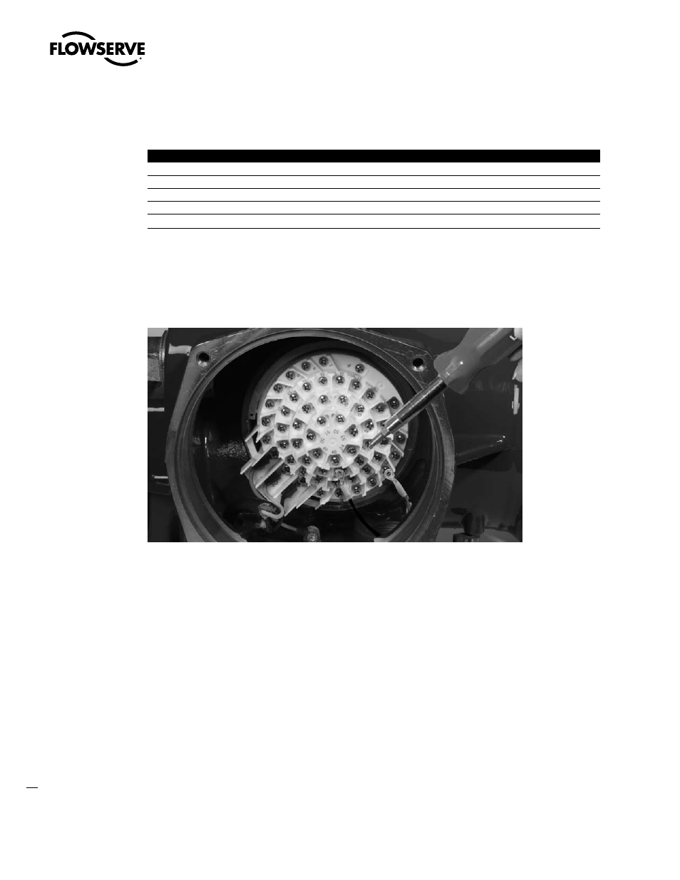
6. Connect the network cables to the MX terminal block as shown in Figure 3.6. Table 3.3 defines each network cable
termination. Refer to Figure 3.8 and 3.9 for topology-specific wiring connections.
Table 3.3 – Network cable terminations
Terminal Block Number
Function
4
NETWORK
5
NETWORK
14
NETWORK
13
NETWORK
3
NETWORK SURGE (EGND)
NOTE: Ground each segment of the cabling at only one point to prevent ground loops, which can affect system
performance. Verify the actuator is properly grounded.
7. Install jumper cable from terminal block pin 3 to earth ground or ground lug.
Figure 3.7 – Connecting network cable to MX terminal block
Advertising
This manual is related to the following products: