System components, 1 introduction, 2 hardware – Flowserve MX-100 Field Unit User Manual
Page 8
MX/DDC-100 Field Unit Installation and Maintenance FCD LMENIM2329-01 – 03/11
8
System Components
2.1 Introduction
This section gives an overview of the components used in the DDC-100 system. The field unit is installed in each MX
actuator. The network cable connects the field unit to the network via the actuator terminal block. The network cable is
connected to a host controller or Master Station II.
2.2 Hardware
NOTE: Recommended storage procedures are detailed in Bulletin FCD LMENIM2314, MX Maintenance and Spare
Parts Manual. Failure to comply with recommended procedures will void the warranty. For longer-term storage,
contact Flowserve for procedures and recommendations.
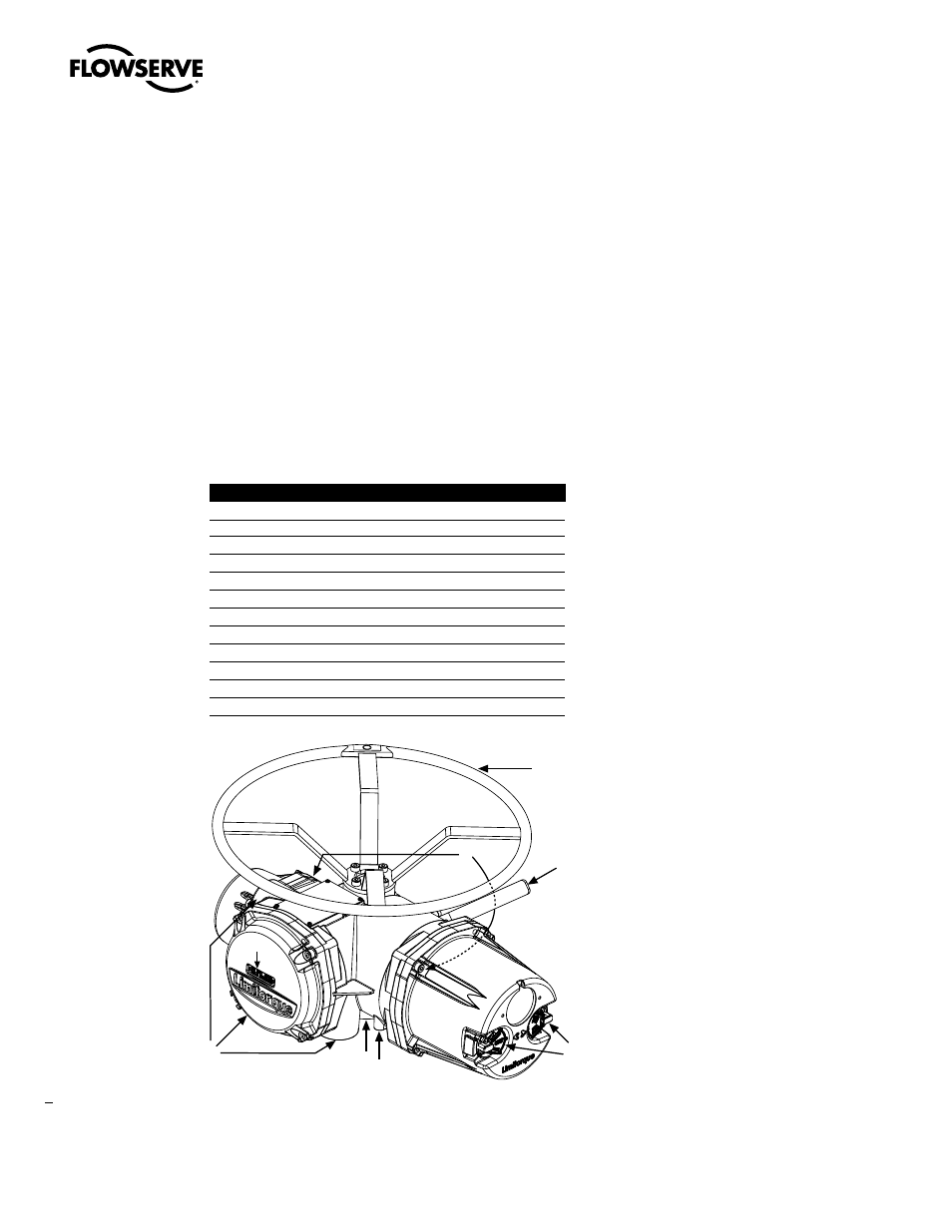
Figure 2.1 – MX-05 actuator
Piece
Description
1
Handwheel
2
Declutch Lever
3
Oil Fills (dotted arrow depicts fill on declutch side)
4
Controls Compartment (field unit location)
5
LCD Display
6
Control Knobs
7
Ground Lug
8
Thrust/Torque Base
9
Conduit Entries
10
Terminal Compartment
11
Motor
12
Nameplate
1
2
3
7
8
4
5
11
12
10
6
9
2