Flowserve MX-100 Field Unit User Manual
Page 28
MX/DDC-100 Field Unit Installation and Maintenance FCD LMENIM2329-01 – 03/11
28
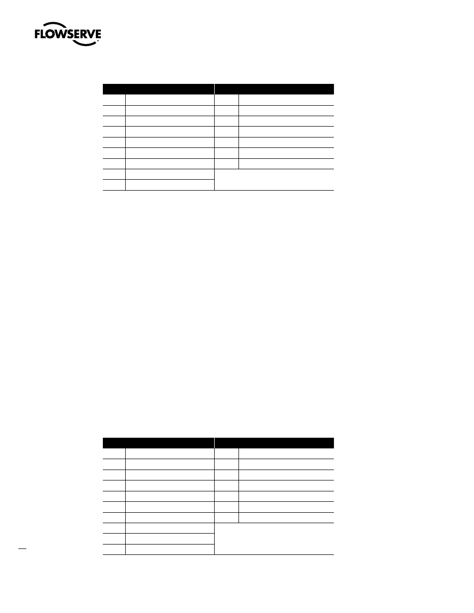
Message Breakdown
Query
Response
01
Slave Address
01
Slave Address
0F
Function
0F
Function
00
Coil Address Hi
00
Coil Address Hi
00
Coil Address Lo
00
Coil Address Lo
00
Quantity of Coils Hi
00
Quantity of Coils Hi
01
Quantity of Coils Lo
01
Quantity of Coils Lo
01
Byte Count
940B
Error Check (LRC or CRC)
01
Force Data Lo
EF57
Error Check (LRC or CRC)
Note: 000000010101h equals Coil Address 00000001 (field unit coil 1)
000100010101h equals Coil Address 00000010 (field unit coil 2)
2.3.11 Modbus Function Code 16 (Preset Multiple Registers)
This function code is used to preset single or multiple registers in the field unit and uses the same predetermined
register values as the function code 06. This function code is typically used to command the DDC-100 Field Unit by
writing values to the 40001 and/or 40002 registers.
Modbus function code 16 command values for controlling the DDC-100 Field Unit are given in Table 2.6. Each
command should be issued only one time for the desired field unit control. Repeated issuance of an acknowledged
command will degrade network performance.
The normal response returns the slave address, function code, starting address, and quantity of registers preset.
NOTE: This function code is implemented in DDC Modbus Firmware 2.00 and greater and MX-DDC Firmware
02/01.00 and greater.
Example of Field Unit Command
Write the command to open an actuator (actuator open) to field unit number 1. This corresponds to writing the value
256 into field unit register 40001.
Query: 011000000001020100A7C0
Response: 01100000000101C9
Message Breakdown
Query
Response
01
Slave Address
01
Slave Address
10
Function
10
Function
00
Starting Address Hi
00
Starting Address Hi
00
Starting Address Lo
00
Starting Address Lo
00
Number of Registers Hi
00
Number of Registers Hi
01
Number of Registers Lo
01
Number of Registers Lo
02
Byte Count
01C9
Error Check (LRC or CRC)
01
Preset Data Hi
00
Preset Data Lo
A7C0
Error Check (LRC or CRC)