Horizontal mount, Fig. 3, Fig. 4 fig. 5 – Greenheck Multi-blade Fire & Combination Fire Smoke Dampers Installation Booklet (826249) User Manual
Page 11: Vertical mount, In. max. [19mm]) sheet metal screws
Horizontal Mount
Damper Model
Maximum Single
Section Size in a
Multiple Section
Assembly
Maximum Over-
all Size for
Multi-Section
Dampers
CFSD-211, 212
24 x 24
NA
DFD-210
32 x 50
128 x 96
DFD-230
32 x 48
72 x 48
DFDAF-310
32 x 50
96 x 50
DFDTF-210
32 x 36
96 x 72
32 x 48
64 x 48 or 32 x 96
FSD-211, 212, 213
36 x 48 or 32 x 50
144 x 96
FSD-211M, 212M
36 x 36
144 x 72
FSD-231
36 x 36 or 32 x 48
72 x 48
FSD-311, 311M, 312,
312M
32 x 50
96 x 50
IMO-310
32 x 50
NA
IMO-311
32 x 50
NA
SEDFD-210,
SEFSD-211
24 x 30
48 x 30
SSFSD-211
24 x 30
48 x 30
FSD-231M
32 x 36
72 x 48
2 in.
Max.
6 in.
Max.
Sleeve
Retaining
Angle
Damper
Duct
Min. 1 in.
Overlap*
Wall or
Floor
Retaining
Angle
*only applicable for damper sizes above 36 in. x 36 in.
6 in.
Max.
2 in.
Max.
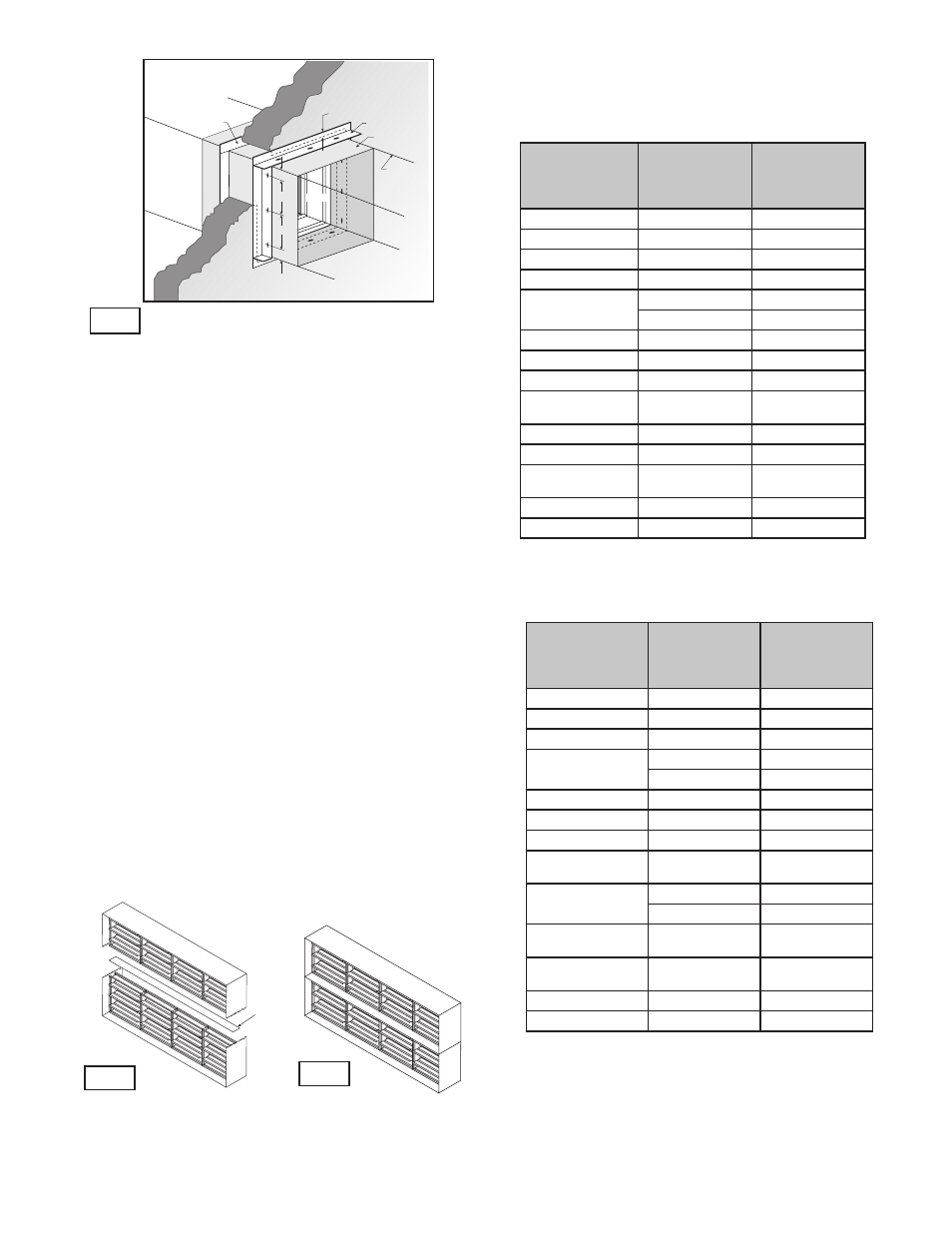
Both vertical and horizontal damper installations are typified by these
drawings.
Fig. 3
5. ACTUATOR CONNECTIONS
Electrical and/or pneumatic connections to damper
actuators should be made in accordance with wiring and
piping diagrams developed in compliance with applicable
codes, ordinances and regulations (see Electrical
Guidelines).
6. INSTALLING MULTIPLE DAMPER SECTION
ASSEMBLIES
A damper assembly is not restricted to a maximum
number of sections, but must not exceed the section
sizes and overall sizes shown (see chart).
Two section high dampers require reinforcement using a
14 gauge (2mm), 5 in. (127mm) wide mullion as shown in
Fig. 4 below, or two individually sleeved units stacked
vertically, shown below in Fig. 5. When using two
individually sleeved units, the sleeve acts as the mullion,
therefore no mullion is required.
The damper sections must be attached together with
#10 (
3
/
4
in. max. [19mm]) sheet metal screws,
1
/
4
in. (6mm)
diameter nuts and bolts, tack or spot welds, or
3
/
16
in.
(48mm) diameter steel pop rivets. Attachments must be
spaced a maximum of 6 in. (152mm) on centers and a
maximum of 2 in. (51mm) from corners. Attachments must
be made on front face and back face (air entering and air
exiting side) of damper sections.
Note: Dampers ordered for individual installation may
not be installed together. The full assembly size must be
specified at the time the dampers are ordered.
14 ga.
5 in. wide
support
mullion
Fig. 4
Fig. 5
Single Sleeve Around Outside with
Support Mullion
Two Individually Sleeved Units
with No Mullions
NOTE:
FSD model dampers fitted with a fusible link closure
device are limited to single section sizes. Dampers with a
fusible link and spring assembly closure device may not be
used for multiple section applications
.
Vertical Mount
Damper Model
Maximum Single
Section Size in a
Multiple Section
Assembly
Maximum
Overall Size for
Multi-section
Dampers
DFD-210
32 x 50
128 x 100
DFD-230
32 x 50
72 x 48
DFDAF-310
32 x 50
128 x 100
DFDTF-210
32 x 36
96 x 72
32 x 50
64 x 50
FSD-211, 212, 213
36 x 48 or 32 x 50
128 x 100
FSD-211M, 212M
36 x 36
128 x 72
FSD-231
36 x 36 or 32 x 48
72 x 48
FSD-311, 311M,
312, 312M
32 x 50
128 x 100
IMO-311
32 x 50
NA
32 x 50
NA
SEDFD-210,
SSDFD-210
24 x 30 or 22 x 36
48 x 30
SEFSD-211
SSFSD-211
24 x 30 or 22 x 36
88 x 72
FSD-331; DFDAF-330
30 x 48
120 x 96
FSD-231M
32 x 36
72 x 48
11