Fig. 9a 41, Fig. 8 – Greenheck Multi-blade Fire & Combination Fire Smoke Dampers Installation Booklet (826249) User Manual
Page 41
12 in.
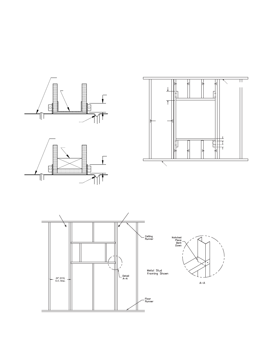
24 in. o.c.
Maximum
Floor Runner
2 in.
Ceiling Runner
2 Panhead
Screws
24 in. o.c.
Maximum
(metal studs)
24 in. o.c.
Maximum
(metal studs)
16 in. o.c.
Maximum
(wood studs)
16 in. o.c.
Maximum
(wood studs)
2 in.
Fig. 9
8. Recommended Preparation of Openings in Wood and Metal Stud Walls
• Frame wall openings as shown. (see Fig. 9 & 9A)
• Gypsum wall board must be fastened 12 in. (305mm) on center to all stud and runner flanges surrounding opening.
(see Fig. 9 & 9A)
• Prepare opening between studs and sleeve assembly as shown below (see Fig. 8).
• All construction and fasteners must meet the requirements of the appropriate wall design (See UL Fire Resistance
Directory) and/or local codes.
IN THIS GROOVE.
RETAINER PLATE
DO NOT PLACE
IN THIS GROOVE.
DO NOT PLACE
RETAINER PLATE
DAMPER FRAME
DAMPER FRAME
WOOD
STUD
MIN
1.00
STUD
METAL
1.00
MIN
Fig. 8
Second set of studs are not required on openings
36 in. x 36 in. (914mm x 914mm) or smaller.
Metal stud only
Fig. 9A
41