Greenheck Multi-blade Fire & Combination Fire Smoke Dampers Installation Booklet (826249) User Manual
Page 4
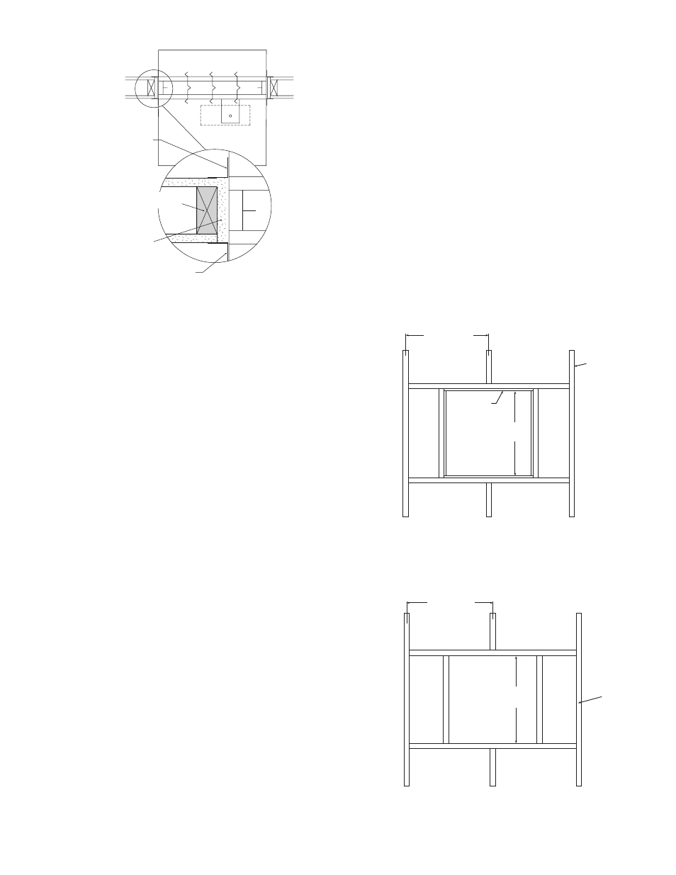
Configuration #3
(Actuator in airstream or out of airstream)
Actuator can be installed either above or below ceiling
construction
2 in. x 4 in. wood
or 2 x 2 1/2 in.
steel studs
Retaining angle
(See Section 3)
Retaining angle
(See Section 3)
Opening lined with UL
rated 5/8 in. gypsum
board (wood studs only)
6. PREPARATION OF OPENINGS IN WOOD AND
METAL STUD CORRIDOR CEILINGS
• Corridor dampers are rated in ceiling
constructions with a fire resistance rating of one
hour.
• Frame openings as shown below. Maximum size
of opening is 24 in. x 24 in. (610mm x 610mm).
See Fig. 1 & 2.
• Corridor ceiling must be covered with a minimum
of one sheet of 5/8 in. (16mm) UL rated gypsum
board on both sides.
• All construction and fasteners must meet the
requirements of the appropriate corridor ceiling
design. Gypsum panels should be attached , 12
in. (305mm) O.C. maximum, to all stud and runner
flanges surrounding opening with fasteners as
designated by the appropriate corridor ceiling
design.
Steel
studs
2 in. x 4 in.
(nominal)
wood studs
Steel Stud Assembly
Wood Stud Assembly
24 in.
max.
24 in. o.c. max.
24 in.
max.
24 in. o.c. max.
Opening lined
with UL rated
5/8 in. gypsum
board
Steel
studs
2 in. x 4 in.
(nominal)
wood studs
Steel Stud Assembly
Wood Stud Assembly
24 in.
max.
24 in. o.c. max.
24 in.
max.
24 in. o.c. max.
Opening lined
with UL rated
5/8 in. gypsum
board
Fig. 1
Fig. 2
4. DUCT TO SLEEVE CONNECTIONS
Dampers are supplied with sleeves and actuators
from the factory and can be installed without the
need for additional field installed sleeves.
Gauge of factory furnished sleeve determines
the type of duct to sleeve connections required.
Any duct connection other than those breakaway
connections described on page three are
considered rigid. Factory furnished round duct
collars on type R and CR are also considered
breakaway.
5. ACTUATOR CONNECTIONS
Electrical and/or pneumatic connections to
damper actuators should be made in accordance
with wiring and piping diagrams developed in
compliance with the job or project design and
specifications.
4