Fig. 2, Fig. 3 – Greenheck Multi-blade Fire & Combination Fire Smoke Dampers Installation Booklet (826249) User Manual
Page 31
Sleeve Gauge
Duct Dimension
Type of Duct
to Sleeve
Connection
Permitted
14 ga. (0.075 in.)
- 10 ga. (0.138
in.)
[2mm - 3.5mm]
All duct sizes
Rigid or
Breakaway
16 ga. (0.060 in.)
[1.5mm]
36 in. (914mm) max. width
24 in. (610mm) max. width
24 in. (610mm) diameter
Rigid only
16 ga. (0.060 in.)
[1.5mm]
All duct sizes
Breakaway only
18 ga. (0.048 in.)
[1.2mm]
85 in. (2159mm) wide and
over
20 ga. (0.036 in.)
[0.9mm]
55 in. - 84 in. wide
(1397mm - 2134mm)
22 ga. (.030 in.)
[0.76mm]
31 in. - 54 in. wide
(787mm - 1372mm)
24 ga. (0.024)
[0.6mm]
13 in. - 30 in. wide
(330mm - 762mm)
26 ga. (0.018 in.)
[0.46mm]
12 in. wide and under
(305mm)
See page 6 for additional information on breakaway sleeve connections.
Sleeve thickness must not be less than the gauge of the connecting duct.
UL Standard 555 requires all ducts to terminate at fire damper sleeves.
4. SECURING THE DAMPER/SLEEVE ASSEMBLY TO
WALL OPENINGS
Damper/sleeve assemblies must be installed in wall
openings using retaining angles on at least one side of
the wall as described below:
• Retaining angles for 11/2 hour rated dampers with a
width and height 48 in. (1219mm) or less must be a
minimum of 20 ga. (1mm). Retaining angles for all 3
hour rated dampers and all dampers with a width or
height greater than 48 in. (1219mm) must be a minimum
of 16 gauge (1.5mm). The leg of the retaining angle
on the damper sleeve shall be a minimum of 11/4 in.
(32mm). The leg of the retaining angle on the wall/floor
shall be long enough to cover the annular space and
overlap the wall/floor by a minimum of 1 in. (25mm).
Damper
Model
Maximum Single
Section Size
Maximum Multiple
Section Size
FSD-311V
50 x 32
100 x 32
Type R and O
Factory Furnished
Duct Collars Qualify
As Breakaway
Connections
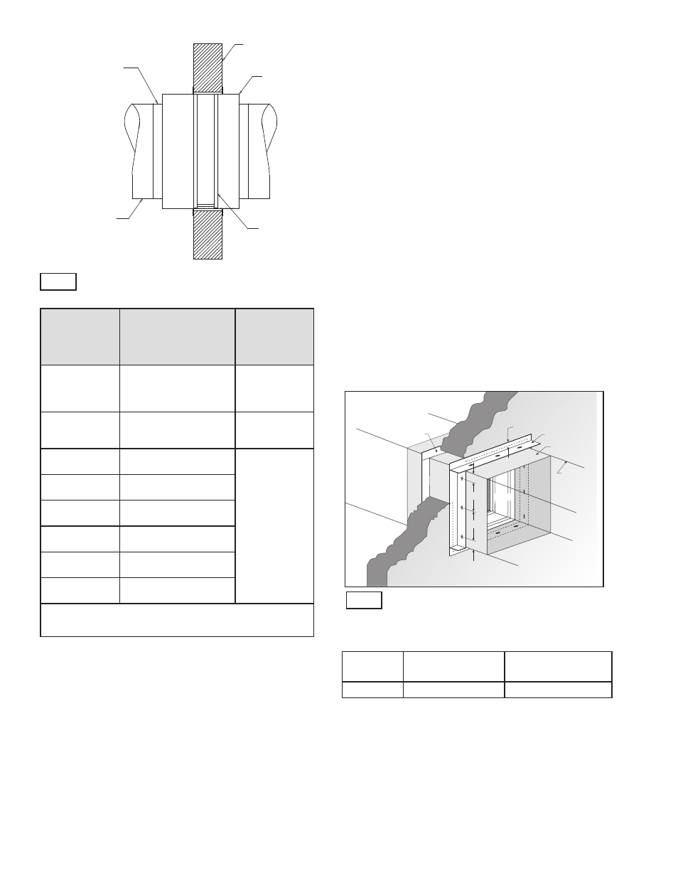
Duct
Damper
Sleeve
Wall or Floor
Type C, O, R
Fig. 2
Damper with type R or O transition factory
furnished.
2 in. Max.
6 in. Max.
Sleeve
Retaining
Angle
Damper
Duct
Min. 1 in.
Overlap*
Wall or
Floor
Retaining
Angle
*only applicable for damper sizes above 36 in. x 36 in.
6 in. Max.
2 in. Max.
Both vertical and horizontal damper installations are
typified by these drawings.
Fig. 3
5. ACTUATOR CONNECTIONS
Electrical and/or pneumatic connections to damper
actuators should be made in accordance with wiring and
piping diagrams developed in compliance with applicable
codes, ordinances and regulations (see Electrical
Guidelines).
• Retaining angle must be attached to the damper using
one or more of the following methods of attachment
(refer to label on outside of sleeve for ‘No Screw’ area):
• Tack or spot welds
• #10 (
3
/
4
in. max. [19mm]) sheet metal screws
•
1
/
4
in. (6mm) bolts and nuts
•
3
/
16
in. (5mm) steel pop rivets
A minimum of two connections per side, top, and bottom,
12 in. (305mm) O.C. (on center) maximum for openings of
48 in. W x 32 in. H (1219mm x 812mm) and less, and 6 in.
(152mm) O.C. for openings 100 in. W x 32 in. H (2540mm
x 32mm) or less. The angles must be attached to all 4
sides of the sleeve with butt joints at each corner. A
minimum of two attachments are required on each side,
top and bottom. Ensure that attachment device does not
interfere with the operation of the damper and the free
movement of the damper blades. The angles need not be
attached to each other at the corners. Do not secure the
retaining angle to the fire separation (see Fig. 3).
• Retaining angles should not be fastened to the wall
material. The angles should only sandwich the wall and
allow for damper expansion during periods of intense
heat.
31