Installation instructions supplement – Greenheck Multi-blade Fire & Combination Fire Smoke Dampers Installation Booklet (826249) User Manual
Page 49
Document number 474015
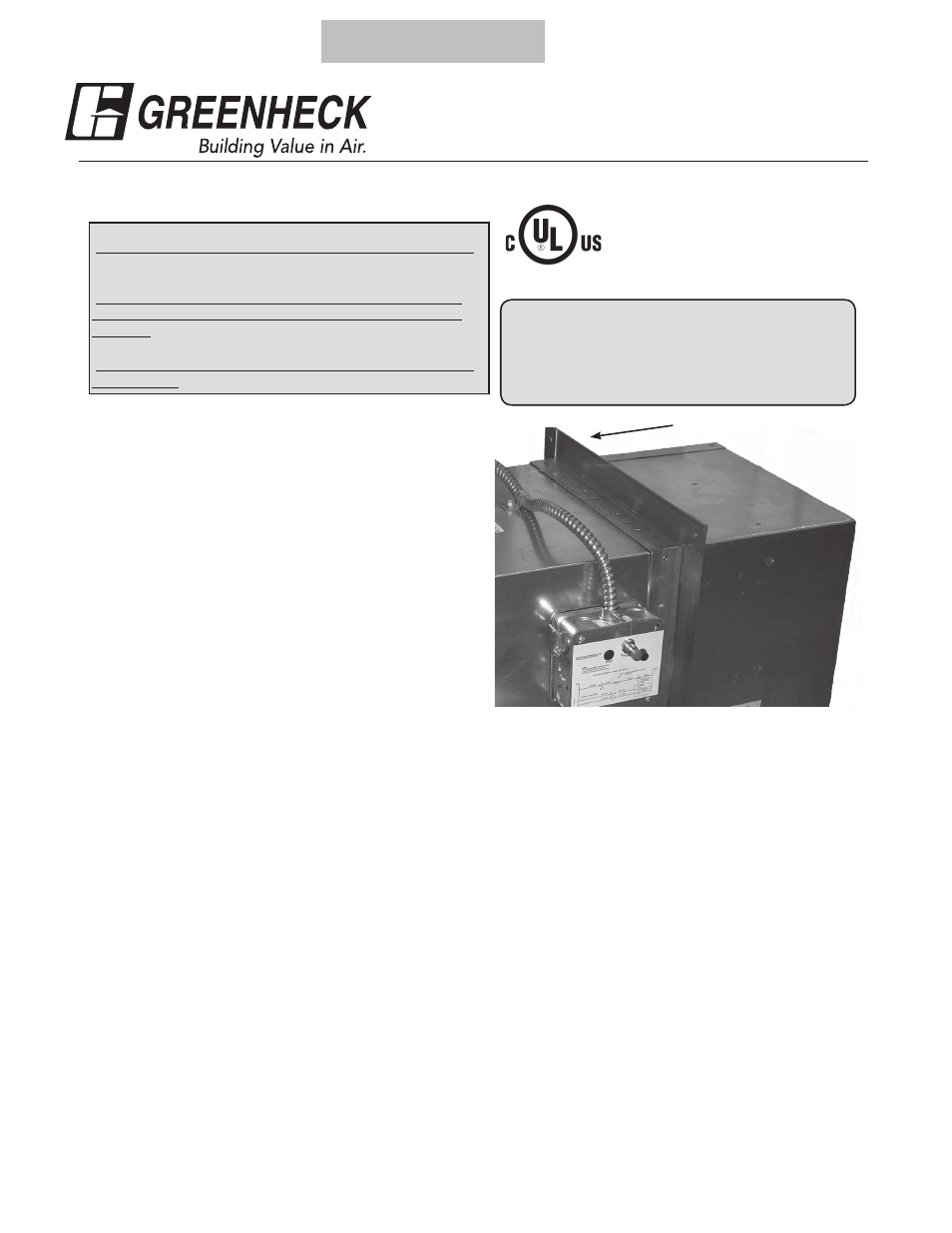
Single Side Retaining Angle
Refer to:
‘Installation Instructions for FD, DFD, SSFD, & KFD Models’
(Part #452763)
or
‘Installation Instructions for FSD-XXX, DFD-XXX, SSFSD-
XXX & CFSD-XXX Series Fire & Combination Fire Smoke
Dampers’ (Part #461336)
or
‘Installation Instructions for FD & DFD 150X Series Curtain
Fire Dampers’ (Part #453946) for additional details.
FD & DFD Series
1
1
/
2
Hour Fire Dampers
and
FSD Series
1
1
/
2
Hour Combination Fire
Smoke Dampers
“UL CLASSIFIED
(see complete marking on product)”
“UL CLASSIFIED to Canadian safety standards
(see complete marking on product)”
Standards UL 555 & 555S
Classifications Filed at UL under Listing #R13317
Single side retaining angle
These instructions apply to 11/2 hour rated combination
fire smoke dampers and curtain fire dampers mounted
in masonry or block walls, metal stud walls, wood
stud walls or concrete floors. Specific requirement in
these instructions are mandatory. These instructions
meet the requirements of NFPA 90A (Standard for
the Installation of Air Conditioning and Ventilating
Systems).
Vertical mount dampers up to a maximum size of 80
in. W x 50 in. H (2032mm x 1270mm), 50 in. W x 80
in. H (1270mm x 2032mm), or 40 in. W x 100 in. H
(1016mm x 2540mm) or horizontal mount dampers up
to a maximum size of 144 in. W x 96 in. H (3658mm x
2438mm) may be installed as illustrated below. Larger
damper assemblies require retaining angles on both
sides of the partition.
Note: Model specific size limits can be found in the
base installation instruction documents noted above
.
1. Clearance Requirements
On vertical mount single side angle installations there
are no minimum clearance requirements between
the wall opening and the damper sleeve. However,
to facilitate installation, clearances between the wall
opening and the damper sleeve are recommended.
On horizontal mount single side angle installations a
minimum clearance is required between the outside of
the damper sleeve and the floor opening of 1/8 in. per
foot (3mm per .3m) of damper width and 1/8 in. per
foot (3mm per .3m) height with a minimum clearance
of 1/4 in. (6mm). The maximum overall clearance is 1
1/2 in. (38mm),
2. Securing the Damper/Sleeve Assembly to Wall/
Floor Opening
Retaining angles must be attached to both the sleeve
and the partition (see figures 1-8).
• Retaining angles for dampers with a width and
height of 48 in. (1219mm) or less must be a
minimum of 20 ga. (1mm). Retaining angles for
Installation Instructions Supplement
dampers with a width or height greater than
48 in. (1219mm) must be a minimum of 16 ga.
(1.5mm). The leg of the retaining angle on the
damper sleeve shall be a minimum of 1 1/4 in.
(32mm). The leg of the retaining angle on the
wall/floor shall be long enough to cover the
annular space and overlap the wall/floor by at
least 1 in. (25mm).
For metal stud partitions only, the single-side
mounting angle may be directly attached to
the metal stud prior to the installation of the
drywall.
• Retaining angles must be attached to the
sleeve using one of the methods shown below:
• tack or spot welds
• #10 sheet metal screws
• 1/4 in. (6mm) nuts and bolts
• Retaining angles must be attached to the
partition using one of the methods shown
below:
• Drywall screws of a length such that the
screw engages the steel stud/track by 1/2
in. (13mm) (steel framing).
®
49
Return to Table of Contents