Installation – Greenheck Multi-blade Fire & Combination Fire Smoke Dampers Installation Booklet (826249) User Manual
Page 3
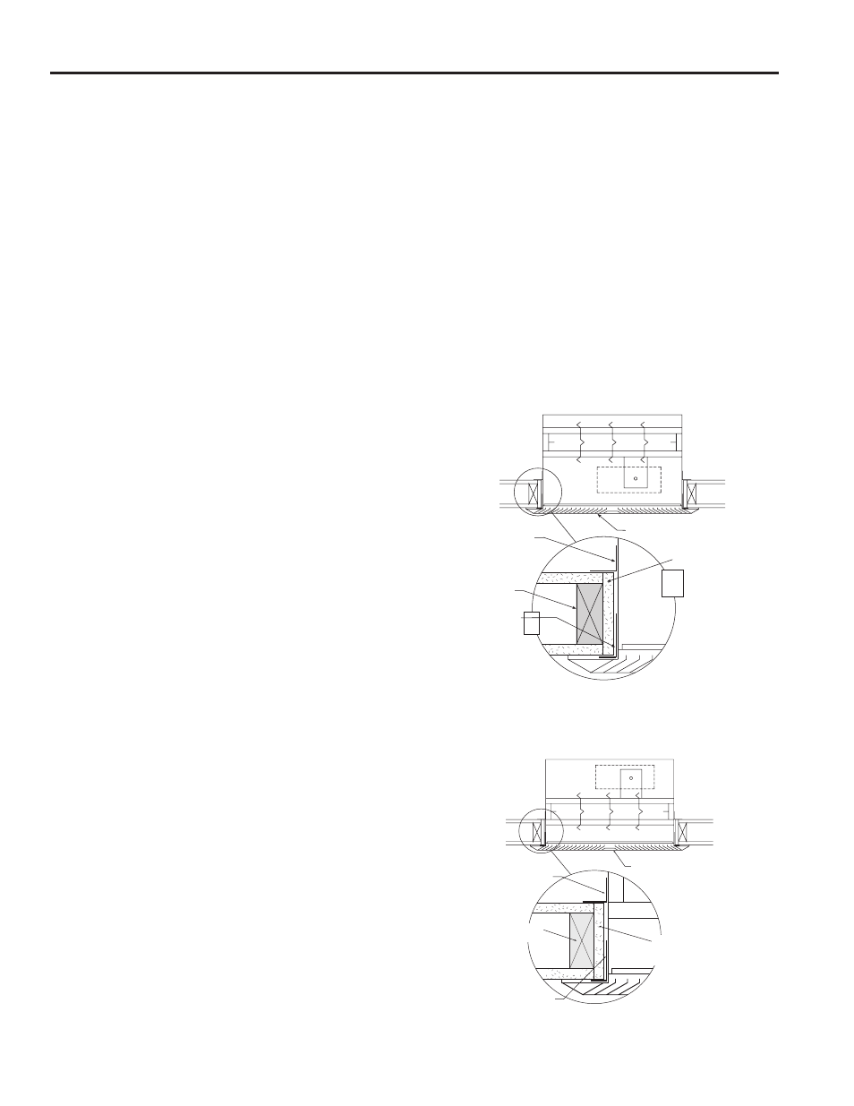
2 in. x 4 in. wood
or 2 x 2 1/2 in.
steel studs
Retaining angle
(See Section 3)
Grille (supplied by others)
1 in. x 2 1/2 in. 16 ga.
angles either inside
or outside of sleeve
Opening lined with UL
rated 5/8 in. gypsum
board (wood studs only)
Configuration #2
(Actuator in airstream or out of airstream)
Retaining angles
(See Section 3)
2 in. x 4 in. wood
or 2 in x 2 1/2 in.
steel studs
1 in. x 2 1/2 in. 16 ga.
angles either inside or
outside of sleeve
Grille (supplied by others)
Opening lined with UL
rated 5/8 in. gypsum
board (wood studs only)
Configuration #1
(Actuator in airstream only)
Allows access to the actuator through the grille or diffuser.
These instructions cover the installation of CFSD-XXX
leakage rated combination fire/smoke dampers with
factory installed actuators and sleeves in corridor
ceiling applications. These instructions meet the
requirements of UL555, UL555S and the Uniform
Building Code.
There are three different configurations available for
this application. Configurations 1 & 2 apply when the
fire rated ceiling is also the finished ceiling and the
damper is installed behind a grille, register or diffuser.
Configuration 3 applies when the fire rated ceiling is
above the finished ceiling and the grille, register or
diffuser is somewhere below the corridor damper.
1. MAXIMUM SIZES
Corridor dampers have a maximum size of
24 in. W x 24 in. H (610mm x 610mm) and a
minimum size of 8 in. W x 6 in. H. (203mm x
152mm).
2. CLEARANCES REQUIRED BETWEEN CORRIDOR
DAMPER SLEEVES AND CEILING OPENINGS
The interior dimension of the prepared ceiling
opening
should be 1/4 in. (6mm) larger than the overall size
of the damper and sleeve assembly.
These are total clearances (ignoring fastener
heads) and do not need to be spaced equally
around the damper.
3. SECURING CORRIDOR DAMPER SLEEVES TO FIRE
RATED CEILING OPENINGS
Corridor damper and sleeve assemblies must
be installed in fire rated ceiling openings using
retaining angles on each side of the ceiling as
described below:
Installation of Configurations 1 & 2:
• Retaining angles must be a minimum of 20 ga.
(1mm)steel and have a minimum of 11/2 in. x 11/4
in. (38mm x 32mm) legs on the ducted side of the
installation and 1 in. x 21/2 in. (25mm x 64mm) legs
on the diffuser, grille or register side.
• The 1 in. x 21/2 in. (25mm x 64mm) angle may be
mounted with the 21/2 in. (64mm) leg inside or
outside the sleeve
Installation of Configuration 3:
• Retaining angles must be a minimum of 20 ga.
(1mm) steel with 11/2 in. x 11/4 in. (38mm x 32mm)
legs.
Retaining angles must be attached to the sleeve
using:
• Tack or spot welds
• No. 10 sheet metal screws
•
1/4 in. (6mm) bolts and nuts
•
3/16 in. (5mm) steel pop rivets
The angles must be attached to all 4 sides of the
sleeve with butt joints at each corner. A minimum of
2 attachments are required on each side, top and
bottom. The angles may (but need not) be attached
to each other at the corners.
• Retaining angles must cover the clearance space
between the sleeve and the ceiling opening.
Installation -
Failure to follow these instructions will void all warranties.
3