Sleeve length and wall/floor thickness, Round duct connections – Greenheck Multi-blade Fire & Combination Fire Smoke Dampers Installation Booklet (826249) User Manual
Page 38
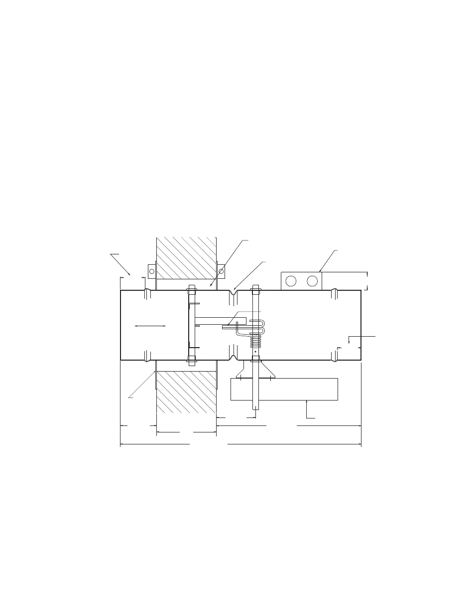
3.375 IN.
FUSIBLE
LINK
LOCATION
CLEARANCE FOR
EXPANSION
TOP VIEW OF DAMPER
6 IN. MAX
SLEEVE LENGTH
TW
DUCT
CONNECTION
AREA
AIRFLOW
2.00 IN.
ACTUATOR
16.00 IN MAX
OPTIONAL BLADE POSITION
INDICATOR AND/OR ELECTRIC
LINK.
DUCT
CONNECTION
AREA
2.00 IN.
1.50 IN.
Optional
Second
Retaining
Plate
Do not place retainer
plate in this groove
Fig. 1
2. SLEEVE LENGTH AND WALL/FLOOR
THICKNESS
Insert the damper assembly into the prepared opening,
to appropriate depth (see Fig. 1).
Recommended maximum and minimum insertion depth
can be exceeded if:
1) the operation of the damper actuator is not
impeded and
2) the
CL of the damper blade remains within
the plane of the wall/floor
IMPORTANT SAFETY DANGER! : To avoid
causing death or serious bodily harm to
building occupants, do not insert screws
into the damper frame unless used for duct
connection within 2 in. (51mm) of the frame
end.
The sleeve may extend a maximum of 16 in. (406mm)
beyond the wall or floor on the actuator side of the
damper and a maximum of 6 in. (152mm) on the
opposite side.
4. SECURING THE DAMPER/SLEEVE ASSEMBLY
TO WALL AND FLOOR OPENINGS
Damper assemblies must be installed in wall/floor
openings using a single retaining plate on either side of
the wall/floor or by using a retaining plate on both sides
of the wall/floor. The use of a second retaining plate is
allowed, but is not necessary. A single retaining plate
is provided with the dampers. A second retaining plate
can be ordered as an option. The outside dimension of
the supplied retainer plate is nominal dia. + 41/2 inches
(114mm).
3. ROUND DUCT CONNECTIONS
Round duct connections to shall be attached with #8 or
#10 sheet metal screws as follows:
• Ducts 22 in. (558mm) dia. and smaller shall have
three screws.
• Ducts larger than 22 in. (558mm) dia. up to and
including 24 in. (610mm) dia. shall have five screws.
NOTE: All connections described may have duct
sealant, PA2084T duct sealant adhesive manufactured
by Precision, DP1010 water base duct sealant
manufactured by Design Polymetrics, Grey Pookie,
Ductmate PROseal®, or CL Ward S Seal applied in
accordance with SMACNA recommendations.
1. CLEARANCES REQUIRED BETWEEN FIRE
DAMPER SLEEVES AND WALL/FLOOR
OPENINGS
Fire damper assemblies expand during periods of
intense heat. Therefore, it is essential that openings in
walls or floors be larger than the fire damper assembly
to allow for this expansion. The wall/floor opening
must be a minimum of 7/8 in. (22mm) larger than the
outside diameter of the damper. Refer to Section 4 for
additional installation considerations.
38