Figure 2 cont – Greenheck Multi-blade Fire & Combination Fire Smoke Dampers Installation Booklet (826249) User Manual
Page 24
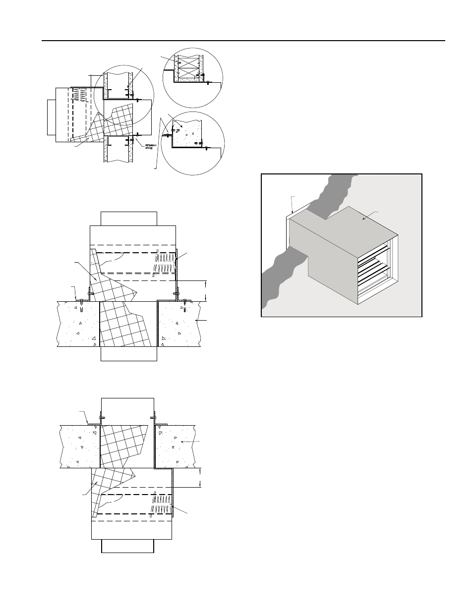
Figure 2 cont....
Type C2- Vertical Mount, Thru Duct with
Single Retaining Angle
Type C2 - Horizontal Mount Above Floor/Wall,
Thru Duct with Single Retaining Angle
Type C2 - Horizontal Mount Below Floor/Wall, Thru
Duct with Single Retaining Angle
7 1/2 in. (191mm)
maximum
Factory Supplied
Thermal Blanket
Wood Stud
Metal Stud
Alternate Retaining
Angle Location
Concrete or
Masonry
Factory Supplied
Thermal Blanket
Retaining
Angle
7 1/2 in. (191mm)
maximum
Damper
Concrete or
Masonry
Retaining
Angle
Factory Supplied
Thermal Blanket
Damper
7 1/2 in. (191mm)
maximum
Concrete or
Masonry
3. DUCT TO SLEEVE CONNECTIONS
Dampers are supplied with actuators (on applicable
models) and sleeves from the factory and can be installed
without the need for additional field installed sleeves.
Sleeve gauges of 20-14 (.9mm - 2mm) are to be used.
UL Standard 555 requires all ducts to terminate at fire
damper sleeves. Sleeve thickness must not be less than
the gauge of the connecting duct.
Duct to sleeve breakaway connections must be of the
type described on page 5. Factory furnished round duct
collars on type R and CR dampers are also considered to
be breakaway connections and may be used.
Thermal Blanket
(installed around entire
outside surface of sleeve)
Wall
Flange
Figure 3: Sleeved damper with Thermal
Blanket (duct termination).
4. SECURING THE DAMPER/SLEEVE ASSEMBLY TO
WALL OPENINGS.
Damper/sleeve assemblies must be installed in wall
openings using flanges and sheet metal screws as
illustrated and described below.
• Flange on front (grille end) of sleeve must be a minimum
of 16 gauge (1.5mm) steel and have a
5
⁄
8
in. (16mm)
minimum flange leg (refer to Figure 3). Using #10
(19mm) sheet metal screws, screw from inside of sleeve
through the rear portion of the studs (as shown in
Figure 1). Space screws a maximum of 6 in. (152mm)
on center and a maximum of 2 in. (51mm) from the
corners (minimum of 2 screws per side). No retaining
angles are required on the side of wall opposite from the
grille.
• Retaining angles for 11/2 hour rated dampers with a
width and height 48 in. (1219mm) or less must be a
minimum of 20 ga. (1mm). Retaining angles for all 3 hour
rated dampers and all dampers with a width or height
greater than 48 in. (1219mm) must be a minimum of 16
gauge (1.5mm). The leg of the retaining angle on the
damper sleeve shall be a minimum of 11/4 in. (32mm).
The leg of the retaining angle on the wall/floor shall be
long enough to cover the annular space and overlap the
wall/floor by a minimum of 1 in. (25mm)(see Figure 4).
24