Greenheck Multi-blade Fire & Combination Fire Smoke Dampers Installation Booklet (826249) User Manual
Page 39
6. CONNECTION AND OPERATION OF
TEMPERATURE RESPONSE DEVICES (Fusible
Link, RRL OPTION, OCI OPTION, TOR
OPTION, and PRV OPTION)
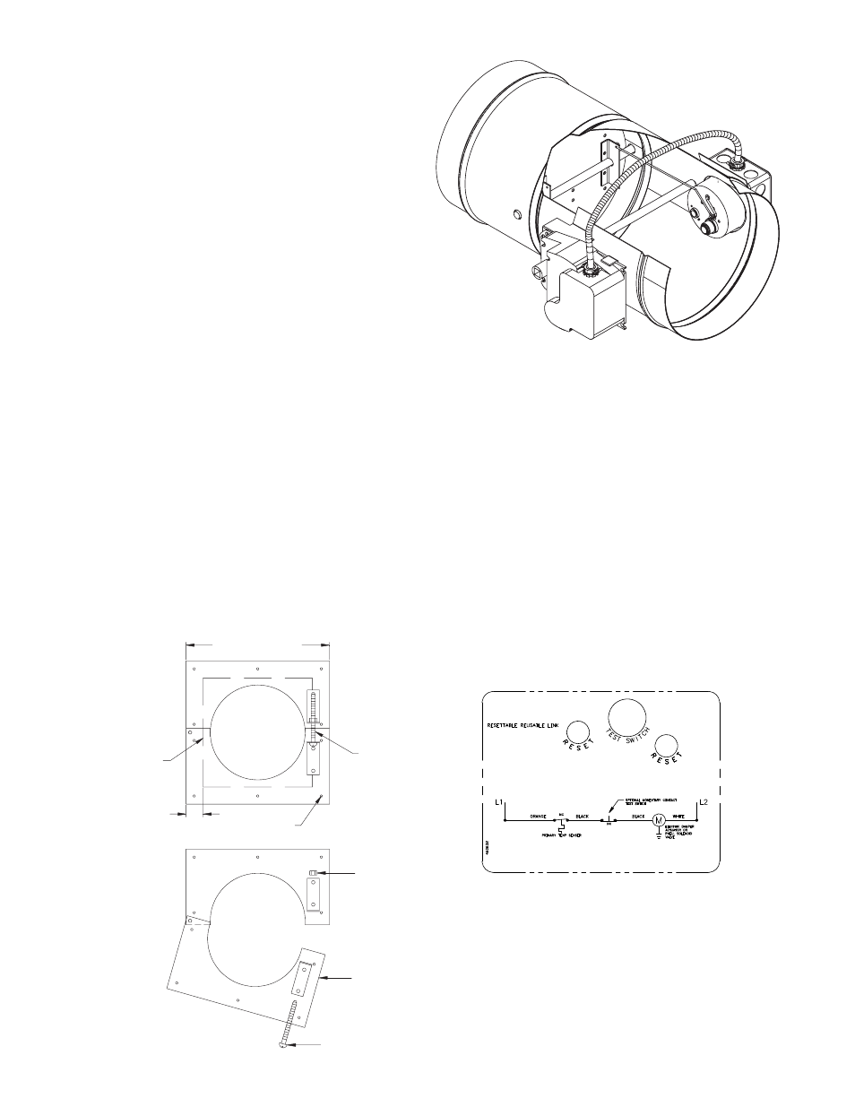
RRL - Dampers will be supplied with a fusible link
temperature response device, as a standard. An
optional thermostat type temperature response
device may have been installed. The device is a RRL
(resettable link device), which only incorporates one
thermostat and therefore the damper remains closed
as soon as its sensor temperature is reached. The
RRL does not contain blade indication switches. Refer
to Fig. 4.
OCI - The OCI (open or closed indicator) option
contains a single pole, double throw switch used
to indicate the damper blade position. The switch
provides a positive open or closed signal when used
in conjunction with remote indicator lights. Refer to
Fig. 5 & 6.
5. ACTUATOR CONNECTIONS
Electrical and/or pneumatic connections to damper
actuators should be made in accordance with wiring
and piping diagrams developed in compliance with
applicable codes, ordinances and regulations (see
Electrical Guidelines).
Opening + 2 in. Min.
1.00 in. Min. Typ.
Fasteners
Clamping
Screw
Nut
Retaining
Plate Assembly
Clamping Screw
Minimum Wall/Floor Opening
= Nominal Dia. + 7/8 in.
Fig. 2
Fig. 3
Fig. 4 RRL Wiring
• The retaining plate(s) will open up for easy
installation when the clamping screw is loosened. If
necessary, remove the clamping screw and nut (see
Fig. 2).
• Position the retaining plate between the blade axle
and the actuator shaft as shown in Figure 1. Do not
place the retaining plate in the groove. IMPORTANT:
The clamping mechanism should face away from the
wall/floor.
• Place the damper and attached retainer plate into
the wall/floor opening.
• If a second retaining plate is being used, secure it
on the opposite side of the wall/floor.
• Verify position, blade orientation, and actuator
clearance then tighten the retainer plate clamping
screws.
• The retainer plate(s) must overlap the wall/floor
opening a minimum of 1 inch (25mm).
• Secure the retainer plate(s) to the wall at the four
corners of each plate when two retainer plates are
used and also within 3/4 in. (19mm) of the center
of each side when one retainer plate is used. The
following fasteners shall be used:
- #8 or #10 screws of a length such that the screw
engages the steel stud/track by 1/2 in. (13mm) (steel
framing)
- #8 or #10 screws of a length such that screw
engages the wood stud by 13/4 in. (44mm) (wood
framing)
- Steel anchors or self tapping concrete screws
penetrating masonry or block 11/4 in. (32mm).
39