Installation – Greenheck Multi-blade Fire & Combination Fire Smoke Dampers Installation Booklet (826249) User Manual
Page 9
These instructions apply to 1
1
/
2
and 3 hour rated combination fire smoke dampers mounted (blades must be horizontal) in: 1)
masonry, block or stud walls and 2) concrete floors or ceilings. Specific requirements in these instructions are mandatory. Dampers
must be installed in accordance with these instructions to meet the requirements of UL 555 and UL 555S. The installation of the
damper and all duct connections to the damper sleeve shall conform to the latest editions of NFPA 90A, Standard for the
Installation of Air Conditioning and Ventilating Systems, and the SMACNA Fire, Smoke and Radiation Damper Installation
Guide, and UL Classifications R13317.
Note: Combination fire smoke dampers are manufactured and labelled for either vertical or horizontal installation. The
dampers must be installed in accordance with labelling.
Installation -
Failure to follow these instructions will void all warranties.
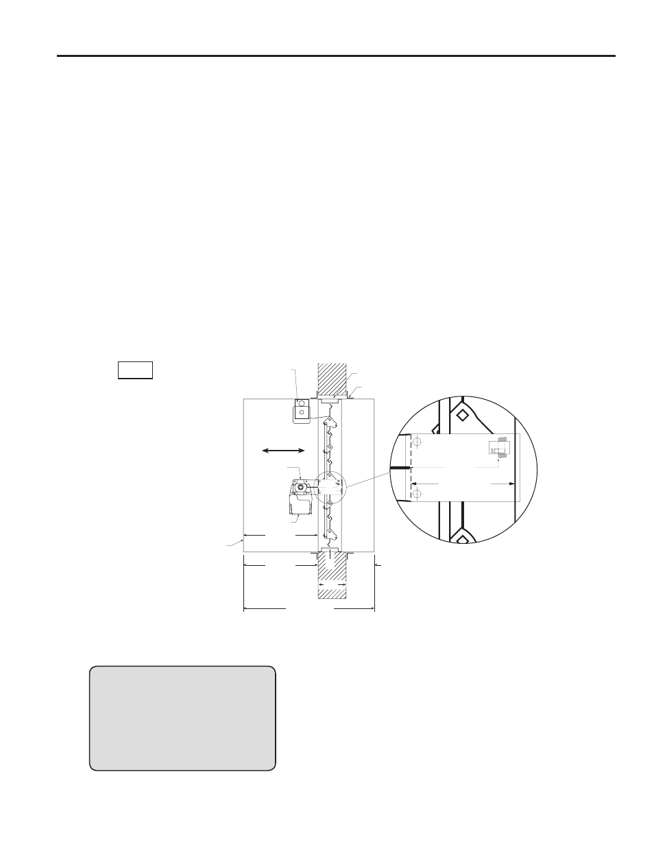
Optional blade indicator
and/or electric link.
LINE OF WALL
DO NOT INSTALL SCREW S
BETWEEN THESE LINES
AROUND ENTIRE DAMPER
Clearance for expansion
(1/4 in. min., 1 1/2 in. max.)
Retaining Angles
(see Section 4)
LIne of Wall
Airflow
Detail 1
DO NOT INSTALL SCREWS
BETWEEN THESE LINES
AROUND ENTIRE DAMPER
Access door required on
jackshaft side of damper.
Refer to the latest edition
of NFPA 90A.
Jackshaft
Actuator
Damper
Sleeve
Sleeve Length (L)
6 in. max.
16 in. max.
‘A’ Dim.
(Distance from
end of sleeve to
face of damper)
458549
Tw
CL
Dampers may be mounted either vertically or horizontally. Blade axis must always be horizontal.
Fig. 1
1. CLEARANCES REQUIRED BETWEEN FIRE DAMPER
SLEEVES AND WALL/FLOOR OPENINGS
Fire damper and sleeve assemblies expand during periods
of intense heat. Therefore, it is essential that openings in
walls or floors be larger than the fire/smoke damper and
sleeve assembly to allow for this expansion. Minimum
clearances required between the outside of fire damper
sleeve assemblies and wall/floor openings are:
• Galvanized steel fire dampers and sleeves:
1
⁄
8
in. per
foot (3mm per .3 m) of damper width and
1
⁄
8
in. per foot
(3mm per .3 m) height with a minimum clearance of
1
⁄
4
in.
(6mm), maximum of 1
1
⁄
2
in. (38mm).
Recommended
clearances, for width and/or height
dimensions of:
1) 48 in. (1219mm) or less:
1
⁄
2
in. (13mm) clearance
2) More than 48 in. (1219mm) and 96 in. (2438mm) or
less: 1 in. (25mm) clearance
3) More than 96 in. (2438mm): 1
1
⁄
2
in. (38mm) clearance
• Stainless steel fire/smoke dampers and stainless steel
or galvanized sleeves:
3
⁄
16
in. per foot (5mm per .3 m) of
damper width and height with a minimum clearance of
1/4 in. (6mm), maximum of 2 in. (51mm).
Recommended
clearances, for width and/or height
dimensions of:
1) 48 in. (1219mm) or less:
3
⁄
4
in. (19mm) clearance.
These are total clearances (ignoring fastener heads) and
do not need to be equally spaced around the damper.
Refer to Section 4 and Figure 6 for additional installation
considerations.
Example:
A 12 in. x 12 in. (305mm x 305mm) will
require a minimum clearance of 1/4
in. (6mm) width and 1/4 in. (6mm) on
height
A 36 in. x 12 in. (914mm x 305mm)
damper will required a minimum
clearance of 1/2 in. (13mm) on width
and 1/4 in. (13mm) on height.
2. SLEEVE LENGTH AND WALL THICKNESS
Insert the sleeved damper assembly into the prepared
opening, to appropriate depth (refer to label on
outside of sleeve for location of damper in wall; see
Dimension A and Detail 1, Fig. 1).
Recommended maximum and minimum insertion depth
can be exceeded if:
1) The operation of the damper is not impeded and
2) The CL of the damper frame remains within the plane
of the wall and
3) Attachments made through the retaining angle do not
penetrate the ‘No Screw’ area designated on the
damper sleeve.
9