Installation – Greenheck Multi-blade Fire & Combination Fire Smoke Dampers Installation Booklet (826249) User Manual
Page 30
These instructions apply to 1
1
/
2
hour rated combination fire smoke dampers mounted (blades must be vertical) in: masonry,
block, or stud walls. Specific requirements in these instructions are mandatory. Dampers must be installed in accordance with
these instructions to meet the requirements of UL555 and UL555S. The installation of the damper and all duct connections
to the damper sleeve shall conform to the latest editions of NFPA 90A, Standard for the Installation of Air Conditioning
and Ventilating Systems, and the SMACNA Fire, Smoke and Radiation Damper Installation Guide, and UL Classifications
R13317.
Installation -
Failure to follow these instructions will void all warranties.
Example: A 12 in. x 12 in. (305mm x 305mm) damper
would require a minimum clearance of
1
/
4
in. (6mm.)
A 36 in. x 12 in. (914mm x 350mm) damper would require
a minimum clearance of
1
/
2
in. (13mm) on width and
1
/
4
in.
(6mm) on height.
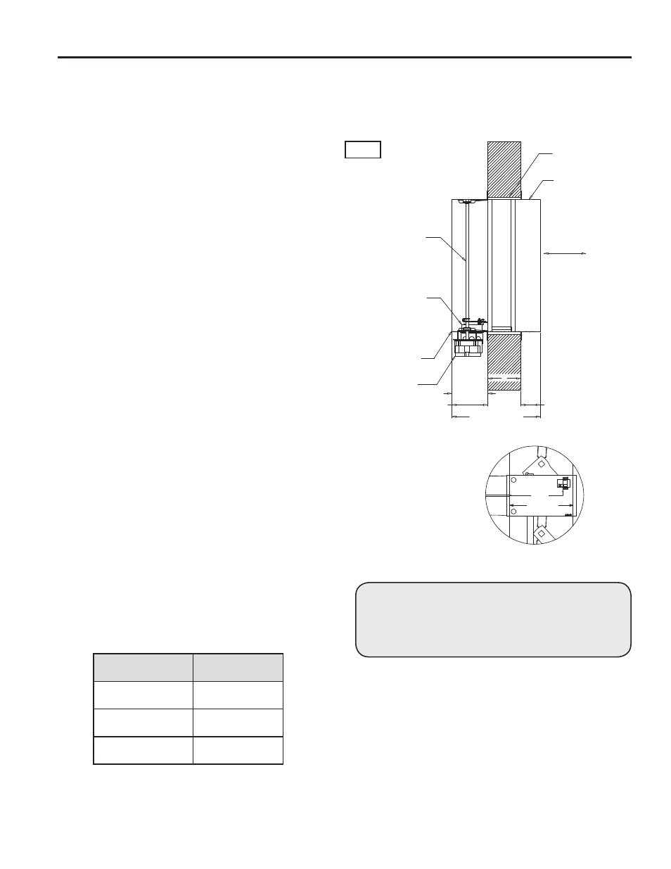
Clearance for Expansion
(1/4in. Min, 1 1/2in. Max.)
Retaining Angles
(See Section 4)
6 in. max.
Detail 1
(Located on Bottom of Damper)
Airlfow
Sleeve Length (L)
16 in. max
"A" Dim.
(Distance from
end of Sleeve to
Face of Damper)
Actuator
Damper
Sleeve
Standard RRL Control Device
with Optional Blade Indication
Jackshaft
Tw
Line of Wall
Do not install screws
between these lines
around entire damper
Fig. 1
1. CLEARANCES REQUIRED BETWEEN FIRE DAMPER
SLEEVES AND WALL/FLOOR OPENINGS
Fire damper and sleeve assemblies expand during
periods of intense heat. Therefore, it is essential that
openings in walls or floors be larger than the fire damper
and sleeve assembly to allow for this expansion.
Minimum clearances required between the outside of fire
damper sleeve assemblies and wall/floor openings are:
• Galvanized steel fire dampers and sleeves:
1
⁄
8
in.
(3mm) per foot of damper width and height with a
minimum clearance of
1
⁄
4
in. (6mm), maximum of 1
1
⁄
2
in. (38mm).
Recommended
clearances, for width and/or height
dimensions of:
1) 36 in. (914mm) or less:
1
⁄
2
in. (13mm) clearance
These are total clearances (ignoring fastener heads) and do
not need to be equally spaced around the damper.
2. SLEEVE LENGTH AND WALL THICKNESS
Insert the sleeved damper assembly into the prepared
opening, to appropriate depth (refer to label on outside
of sleeve for location of damper in wall; see Dimension A
and Detail 1, Fig. 1).
Recommended maximum and minimum insertion depth
can be exceeded if:
1) The operation of the damper is not impeded and
2) The CL of the damper frame remains within the plane of
the wall and
3) Attachments made through the retaining angle do
not penetrate the ‘No Screw’ area designated on the
damper sleeve.
IMPORTANT: To avoid causing death or serious bodily
harm to building occupants, do not penetrate the ‘No
Screw’ area designated on the damper sleeve or the
damper may not close properly.
The sleeve may extend a maximum of 16 in. beyond the
wall on the actuator side of the damper and a maximum
of 6 in. on the opposite side. Recommended standard
sleeve lengths for various wall thicknesses are:
Clearance for Expansion
(1/4in. Min, 1 1/2in. Max.)
Retaining Angles
(See Section 4)
6 in. max.
Detail 1
(Located on Bottom of Damper)
Airlfow
Sleeve Length (L)
16 in. max
"A" Dim.
(Distance from
end of Sleeve to
Face of Damper)
Actuator
Damper
Sleeve
Standard RRL Control Device
with Optional Blade Indication
Jackshaft
Tw
Line of Wall
Do not install screws
between these lines
around entire damper
Wall Thickness
Dimension (T
W
)
Sleeve Length
Dimension (L)
4 - 6 in.
(102mm - 152mm)
16 in.
(406mm)
7 - 10 in.
(178mm - 254mm)
21 in.
(533mm)
11 - 13 in.
(279mm - 330mm)
24 in.
(610mm)
3. DUCT TO SLEEVE CONNECTIONS
Dampers are supplied with sleeves and actuators from
the factory and can be installed without the need for
additional field installed sleeves.
Gauge of factory furnished sleeve determines the type
of duct to sleeve connections required (see table below).
Any duct connection other than those breakaway
connections described on page 31 are considered rigid.
Factory furnished duct collars, type R and O, are also
considered breakaway (see Fig. 2).
30