Duct continues” horizontal or vertical mount – Greenheck Multi-blade Fire & Combination Fire Smoke Dampers Installation Booklet (826249) User Manual
Page 18
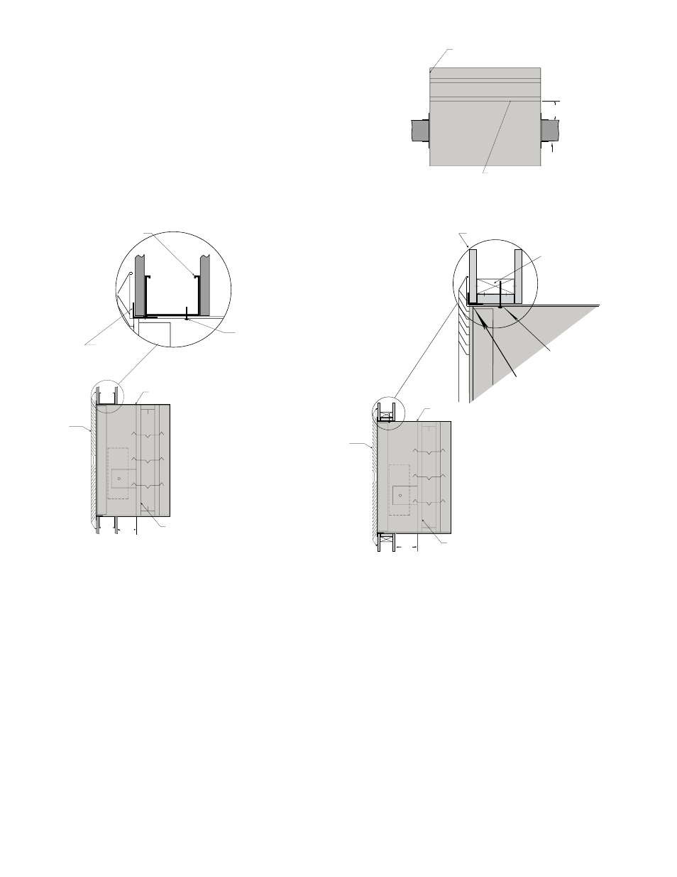
1. DAMPER IS INSTALLED OUTSIDE OF WALL PLANE
OFSD-XXX
Figure 1 shows two approved installations for
combination fire smoke dampers: 1) “Through the
grille access” and 2) installation in continuing duct.
To provide “through the grille” access to the damper
actuator, the damper is located toward the back of the
sleeve and the actuator is installed between the damper
and grille. Actuator and damper can be accessed and
serviced by removing the grille. To provide access to the
damper actuator for continuing ductwork, refer to the
requirements of NFPA 90A.
Steel stud
Flange
Grille
(Supplied
by others)
Factory Supplied
Thermal Blanket
Factory Supplied
Thermal Blanket
7 1/2 in.
Max.
7 1/2 in.
Max.
Damper
Damper
#10 2 1/2 in. long sheet metal
screws spaced 6 in. on center
and maximum of 2 in. from the
corners (minimum of 2 screws
per side) through the sleeve into
the header, sill and jamb framing
members. Screw into rear
portion of the studs so as to
avoid space conflicts with the
grille assembly.
Masonry
floor
“Duct Continues”
Horizontal or Vertical Mount
Wooden Stud Construction
Gypsum Wallboard
Stud or Runner
Retaining Angle
(Refer to section 4)
(Duct Terminates)
In wood stud construction,
gypsum wallboard must cover
all wood stud surfaces.
Grille
(Supplied
by others)
Factory Supplied
Thermal Blanket
Fire damper or
combination fire
smoke damper
6 1/2 in.
Max.
#10 sheet metal screws, 2
1/2 inches long, spaced
6 in. on center and
maximum of 2 in. from
corners (minimum of 2
screws per side). Screw
into rear portion of the
studs so as to avoid
space conflicts with
the grille assembly.
Figure 1: Installation configurations for ‘Out of Wall’ combination fire smoke dampers.
“Duct Terminates” Wood Stud
“Duct Terminates” Metal Stud
Steel stud
Flange
Grille
(Supplied
by others)
Factory Supplied
Thermal Blanket
Factory Supplied
Thermal Blanket
7 1/2 in.
Max.
7 1/2 in.
Max.
Damper
Damper
#10 2 1/2 in. long sheet metal
screws spaced 6 in. on center
and maximum of 2 in. from the
corners (minimum of 2 screws
per side) through the sleeve into
the header, sill and jamb framing
members. Screw into rear
portion of the studs so as to
avoid space conflicts with the
grille assembly.
Masonry
floor
Note: Both installations for vertical mount.
ODFD-XXX, OFD-XXX, and OSSFD-XXX: Figure 2
shows installations that are also approved for curtain fire
dampers. For access to inspect the damper and fusible
link, refer to the requirements of NFPA 90A.
2. CLEARANCE REQUIREMENTS
There is no minimum clearance requirement between
the wall/floor opening and the sleeve exterior (with
thermal blanket attached). However, to facilitate
installation, clearances between the wall/floor opening
and the damper sleeve are recommended. although
there is no maximum allowable clearance, the minimum
overlap requirements between the wall/floor and the
flange/retaining angle must be met. On grill mount
installations the flange must overlap the wall/floor by
1/2 in. (13mm). On continuous duct installations, the
retaining angles must overlap the wall/floor by 1 in.
(25mm). Because no clearances are required between
the wall/floor opening and the sleeve, dampers may not
be installed in the plane of the wall using this installation
method.
18