Grass Valley LVS 100 v.3.15 User Manual
Page 309
Advertising
Removal and Installation Procedures
Profile LVS Event Management System Instruction Manual
9-19
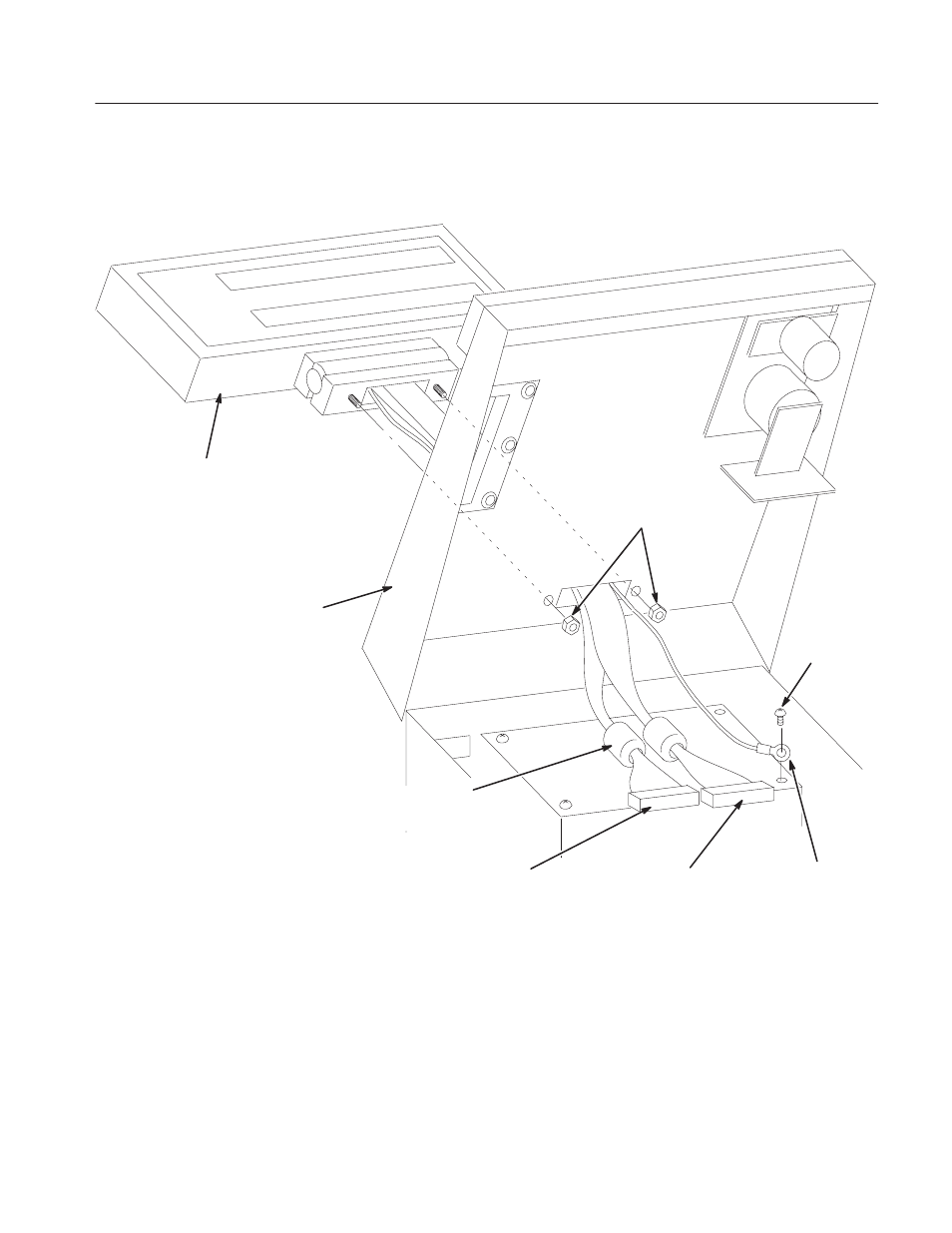
J110 (Back cable from
the lower LCD)
J111 (Front cable from
the upper LCD)
Ground Lead
going to power
supply chassis
Nuts M4 7MM,
HEX 2
LCD Module
Ferrite core. Remove
before pulling the cables
through the hole.
Operation Panel
(Top Cover)
Screw M3 6MM,
PNH
Figure 9-9: LCD Module Removal
Advertising
This manual is related to the following products: