Connector pin arrangement, Standard cable wiring table, Cn1 connector pin arrangement – Yaskawa MP3200iec User Manual
Page 46: Cn2 connector pin arrangement, 19 option module - ai-01 (analog input) module, Pin arrangement viewed from wiring side
19 Option Module - AI-01 (Analog Input) Module
44
YASKAWA America, Inc. MP3200iec Hardware Manual YAI-SIA-IEC-5
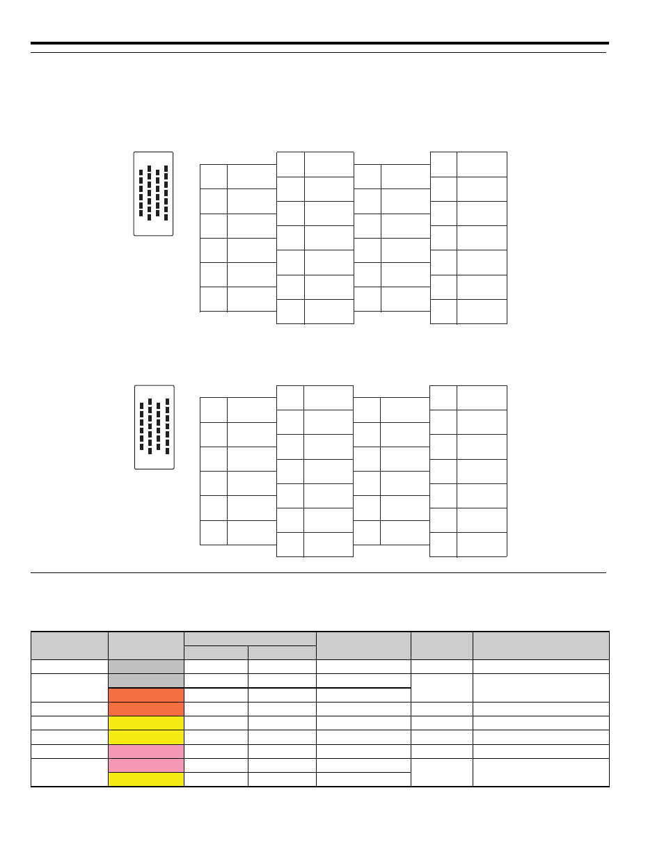
Connector Pin Arrangement
The AI-01 Module Connector (CN1/CN2) pin arrangement is shown below.
CN1 Connector Pin Arrangement
Pin Arrangement Viewed from Wiring Side
CN2 Connector Pin Arrangement
Pin Arrangement Viewed from Wiring Side
Standard Cable Wiring Table
The wiring table for the standard cable JEPMC-W6080- is shown below.
Pin
Wire Color
Marking
Label on Marking
Tube
Signal Name
Function
Color
Marking
1
Gray
Red
– – –
V1/V5
V1/V5
Voltage input 1/5
2
Gray
Black
– – –
G1V/G5V
G1/G5
Ground 1/5
Orange
Red
– – –
G1A/G5A
3
Orange
Black
– – –
A1/A5
A1/A5
Current input 1/5
14
Yellow
Red
–
DP1/DP5
MDP1/MDP5
Mode switching terminal 1/5
16
Yellow
Black
–
DN1/DN5
MDN1/MDN5
Mode switching terminal 1/5
4
Pink
Red
– –
V2/V6
V2/V6
Voltage input 2/6
5
Pink
Black
– –
G2V/G6V
G2/G6
Ground 2/6
Yellow
Black
– –
G2A/G6A
25
26
13
12
15
1
2
14
1
V1
14
MDP1
2
G1
15
G1
3
A1
16
MDN1
4
V2
17
MDP2
5
G2
18
G2
6
A2
19
MDN2
7
V3
20
MDP3
8
G3
21
G3
9
A3
22
MDN3
10
V4
23
MDP4
11
G4
24
G4
12
A4
25
MDN4
13
26
25
26
13
12
15
1
2
14
1
V5
14
MDP5
2
G5
15
G5
3
A5
16
MDN5
4
V6
17
MDP6
5
G6
18
G6
6
A6
19
MDN6
7
V7
20
MDP7
8
G7
21
G7
9
A7
22
MDN7
10
V8
23
MDP8
11
G8
24
G8
12
A8
25
MDN8
13
26