Danger – Yaskawa MP3200iec User Manual
Page 56
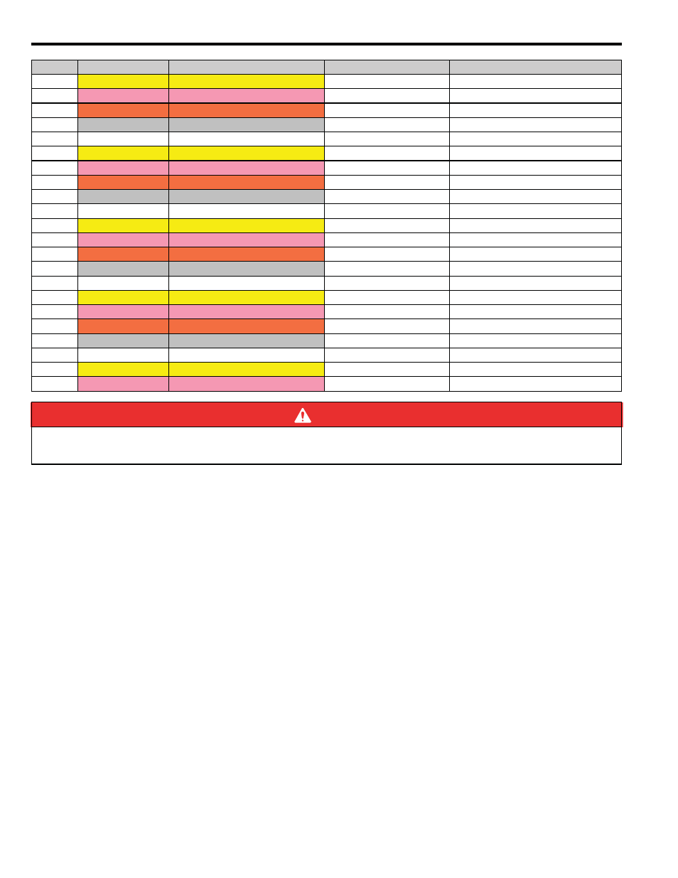
21 Option Module - DO-01 (Digital Output) Module
54
YASKAWA America, Inc. MP3200iec Hardware Manual YAI-SIA-IEC-5
29
Yellow
—
DO_05/37
Digital output 5/37
30
Pink
—
DO_07/39
Digital output 7/39
31
Orange
— —
0V_1/5
Common ground 1/5
32
Gray
— —
0V_2/6
Common ground 2/6
33
White
— —
DO_09/41
Digital output 9/41
34
Yellow
— —
DO_11/43
Digital output 11/43
35
Pink
— —
DO_13/45
Digital output 13/45
36
Orange
— — —
DO_15/47
Digital output 15/47
37
Gray
— — —
0V_2/6
Common ground 2/6
38
White
— — —
0V_3/7
Common ground 3/7
39
Yellow
— — —
DO_17/49
Digital output 17/49
40
Pink
— — —
DO_19/51
Digital output 19/51
41
Orange
— — — Continuous
DO_21/53
Digital output 21/53
42
Gray
— — — Continuous
DO_23/55
Digital output 23/55
43
White
— — — Continuous
0V_3/7
Common ground 3/7
44
Yellow
— — — Continuous
0V_4/8
Common ground 4/8
45
Pink
— — — Continuous
DO_25/57
Digital output 25/57
46
Orange
— — — —
DO_27/59
Digital output 27/59
47
Gray
————————
DO_29/61
Digital output 29/61
48
White
————————
DO_31/63
Digital output 31/63
49
Yellow
————————
0V_4/8
Common ground 4/8
50
Pink
————————
N.C
DANGER
Columns “Signal Name” and “Function” display the values for connectors CN1 and CN2 in the format “CN1/CN2”
respectively.
Pin
Wire Color
Marking
Signal Name
Function