Yaskawa VCD 723 User Manual
Page 61
4
Troubleshooting/Maintenance
55
Fault and Error Conditions
9/15/93
ERROR/FAULT
PROBABLE CAUSE
CORRECTIVE ACTION
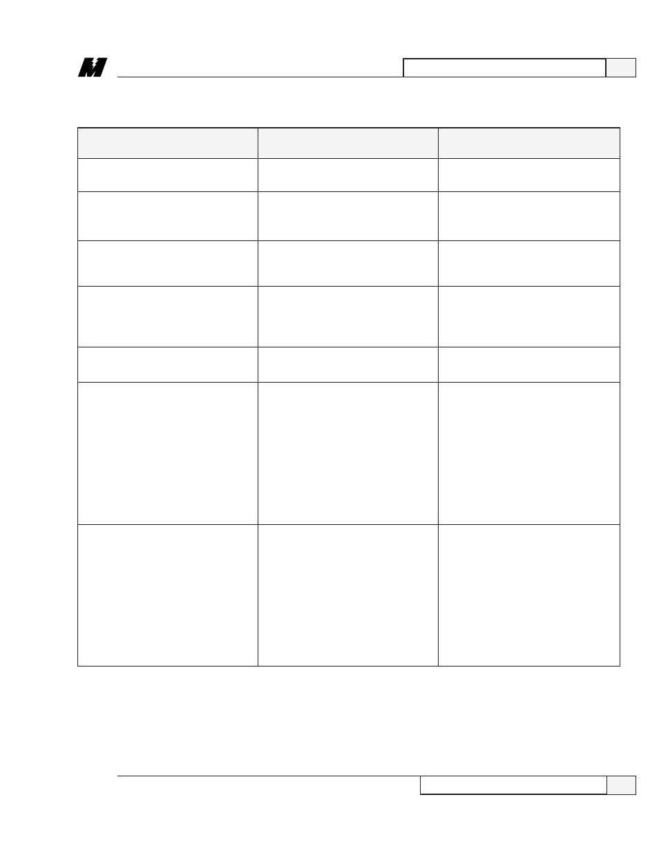
Replace the inverter control circuit card
or the connecting cable.
Replace the inverter control circuit
card.
Replace the inverter control circuit
card.
➊
Cycle power off and on.
❷
Replace the cable between the
MicroTrac card and the drive.
❸
Replace MicroTrac circuit card.
Replace the inverter control circuit
card.
Verify all of the constant settings.
Replace the MicroTrac circuit card.
Whenever changing parameter settings
the following procedure must be
followed:
➊
Correct the setting.
❷
Use function 994 to transfer the
data from RAM to NVRAM.
❸
Turn power off.
❹
When the charge light is off, then
turn power on.
Verify all of the lettered constant
settings. Whenever changing parameter
settings the following procedure must
be followed:
➊
Correct the setting.
❷
Use function 994 to transfer the
data from RAM to NVRAM.
❸
Turn power off.
❹
When the charge light is off, then
turn power on.
Table 8. Standard Error and Fault Descriptions - Continued
745, OPTION CARD CONN
751, DSP P CKT FLT
752, OPTION A/D FLT
753, MISSING DCU
754, INV MODEL ERROR
760, DPRAM CHECKSUM
761, DPRAM CONST. ERR
Drive detected that its optional card
connector has failed.
Drive detected that its Digital Signal
Processor (DSP) peripheral circuitry
has failed.
Drive declared that the A/D converter
on its High Accuracy Torque Control
option card has failed.
Drive has not received a software
handshake from the MicroTrac circuit
card.
Drive declared that the model number
is wrong.
Drive declared that the checksum
validating the constants in the Dual
Port RAM (between the MicroTrac
card and the inverter) is incorrect.
Drive declared that a constant in the
Dual Port RAM (between the
MicroTrac card and the inverter) is out
of range.