Yaskawa VCD 723 User Manual
Page 63
4
Troubleshooting/Maintenance
57
Fault and Error Conditions
9/15/93
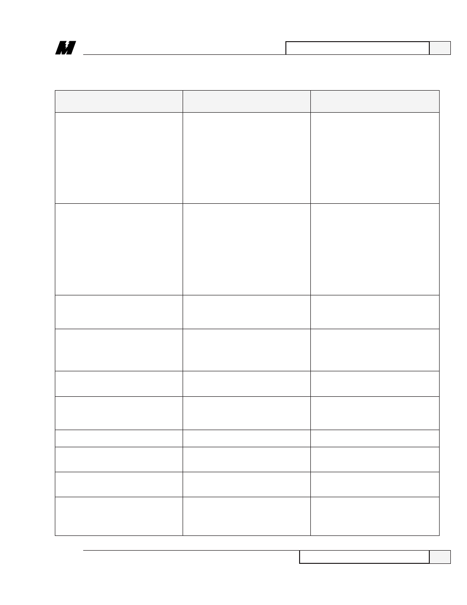
ERROR/FAULT
PROBABLE CAUSE
CORRECTIVE ACTION
Replace the inverter control circuit
card. Whenever changing parameter
settings the following procedure must
be followed:
➊
Correct the setting.
❷
Use function 994 to transfer the
data from RAM to NVRAM.
❸
Turn power off.
❹
When the charge light is off, then
turn power on.
Verify all of the lettered constant
settings. Whenever changing parameter
settings the following procedure must
be followed:
➊
Correct the setting.
❷
Use function 994 to transfer the
data from RAM to NVRAM.
❸
Turn power off.
❹
When the charge light is off, then
turn power on.
Refer to troubleshooting chart 7.
Refer to troubleshooting chart 5.
Refer to troubleshooting chart 8.
Refer to troubleshooting chart 10.
Check for a short circuit in the output.
Check for problems in the drive to
motor wiring.
Replace the inverter control circuit
card.
Refer to troubleshooting chart 8.
Table 8. Standard Error and Fault Descriptions - Continued
766, INV NV RAM ERR
767, OUT OF RANGE
768, OVERCURRENT
769, BUS OVERVOLTAGE
770, INV. OVERLOAD
771, INVERTER HOT
772, BLOWN FUSE
773, OPEN LOAD PHASE
774, INV HARDWARE FLT
775, MOTOR OVERLOAD
Drive has declared an error in writing
to its non-volatile RAM.
Drive declared a value is out of range.
Drive has detected that the output
current exceeds 200% of the transistor
rated current.
Drive has detected that the DC bus
voltage is high. The detection level is
approximately 400V for a 230V rated
unit; 800V for a 460V rated unit.
Drive detected that the Drive overload
protection has tripped.
Drive detected that the fin temperature
has exceeded 90 degrees C (194
degrees F) +/-5 degrees.
DC Bus fuse has cleared.
Drive detected an opening in the
wiring from the inverter to the motor.
Drive detected a fault in its control
circuit hardware.
Drive detected that the motor overload
protection has tripped.