Yaskawa VCD 723 User Manual
Page 85
Advertising
Appendices
79
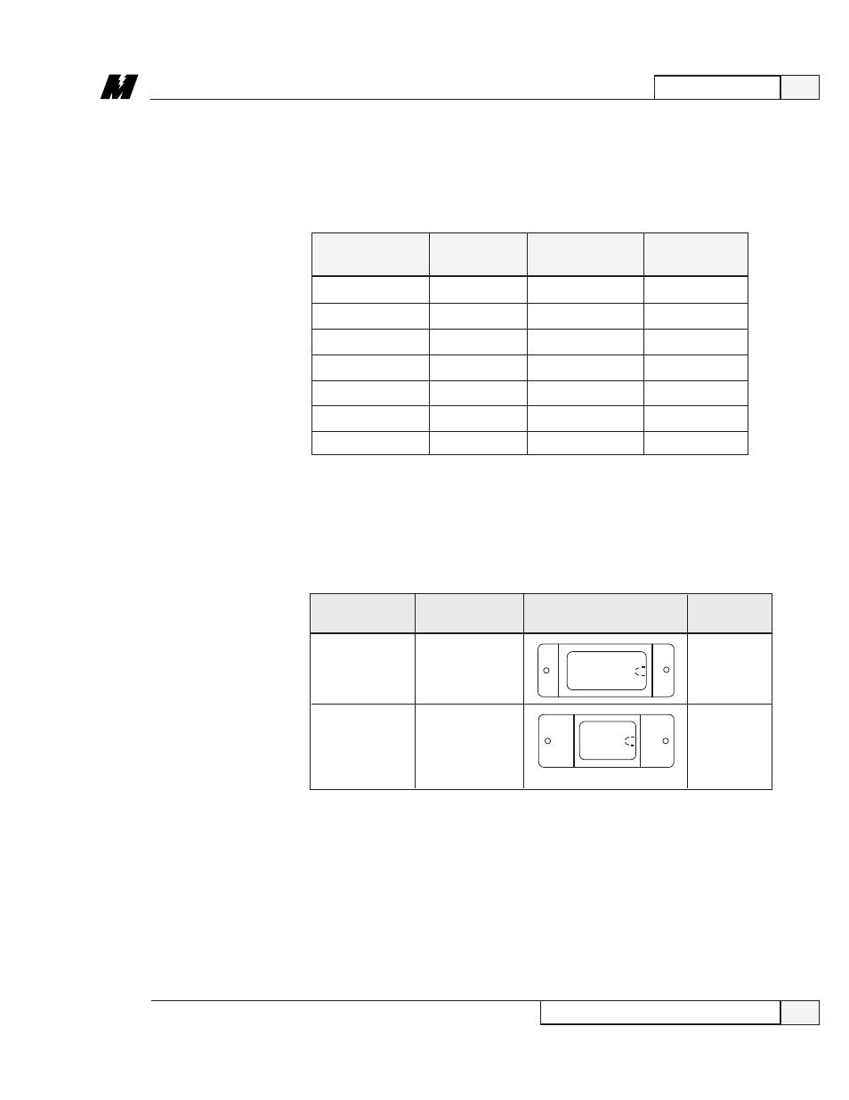
VCM Motor/PG Connection
9/15/93
+12V (200mA)
1
White
Red
0V
2
Black
Black
A+
3
Red
Yellow
A–
4
Green
Wht/Yel
B+
5
Brown
Blue
B–
6
Yellow
Wht/Blue
SHIELD
7
Shield
Green
TB1
EPC
BEI
FUNCTION
TERMINAL
MODEL 755A
(1)
MODEL E25
Table 15. TB1 - PG Connection
CONNECTOR
FUNCTION
TERMINAL
WIRE
NO.
ARRANGEMENT
(2)
SIZE
Table 16. Connectors on PG Card
CA1
For Pulse
Generator
CA2
For Pulse
Monitor
18 GA
(0.75 mm2)
18 GA
(0.75 mm2)
(1) For PG, EPC Model 755A (provided as standard), Orange and Blue
wires are not used.
1 2 3
4 5
6 7 8
6 7 8
4 5
1 2 3
Pulse Generator connections are shown in the following tables.
(2) Top view (from pin connections).
Advertising
See also other documents in the category Yaskawa Equipment:
- Tag Generator (30 pages)
- MP3300iec (82 pages)
- 1000 Hz High Frequency (18 pages)
- 1000 Series (7 pages)
- PS-A10LB (39 pages)
- iQpump Micro User Manual (300 pages)
- 1000 Series Drive Option - Digital Input (30 pages)
- 1000 Series Drive Option - CANopen (39 pages)
- 1000 Series Drive Option - Analog Monitor (27 pages)
- 1000 Series Drive Option - CANopen Technical Manual (37 pages)
- 1000 Series Drive Option - CC-Link (38 pages)
- 1000 Series Drive Option - CC-Link Technical Manual (36 pages)
- 1000 Series Drive Option - DeviceNet (37 pages)
- 1000 Series Drive Option - DeviceNet Technical Manual (81 pages)
- 1000 Series Drive Option - MECHATROLINK-II (32 pages)
- 1000 Series Drive Option - Digital Output (31 pages)
- 1000 Series Drive Option - MECHATROLINK-II Technical Manual (41 pages)
- 1000 Series Drive Option - Profibus-DP (35 pages)
- AC Drive 1000-Series Option PG-RT3 Motor (36 pages)
- Z1000U HVAC MATRIX Drive Quick Start (378 pages)
- 1000 Series Operator Mounting Kit NEMA Type 4X (20 pages)
- 1000 Series Drive Option - Profibus-DP Technical Manual (44 pages)
- CopyUnitManager (38 pages)
- 1000 Series Option - JVOP-182 Remote LED (58 pages)
- 1000 Series Option - PG-X3 Line Driver (31 pages)
- SI-EN3 Technical Manual (68 pages)
- JVOP-181 (22 pages)
- JVOP-181 USB Copy Unit (2 pages)
- SI-EN3 (54 pages)
- SI-ET3 (49 pages)
- MECHATROLINK-III (35 pages)
- EtherNet/IP (50 pages)
- SI-EM3 (51 pages)
- 1000-Series Option PG-E3 Motor Encoder Feedback (33 pages)
- 1000-Series Option SI-EP3 PROFINET (56 pages)
- PROFINET (62 pages)
- AC Drive 1000-Series Option PG-RT3 Motor (45 pages)
- SI-EP3 PROFINET Technical Manual (53 pages)
- A1000 Drive Option - BACnet MS/TP (48 pages)
- 120 Series I/O Modules (308 pages)
- A1000 12-Pulse (92 pages)
- A1000 Drive Software Technical Manual (16 pages)
- A1000 Quick Start (2 pages)
- JUNMA Series AC SERVOMOTOR (1 page)
- A1000 Option DI-101 120 Vac Digital Input Option (24 pages)