Yaskawa VCD 723 User Manual
Page 93
Appendices
87
Node, Channel and Subchannel Assignments
9/15/93
SN-02 Setting
SN-02 is factory set for “FFF” hex (4095 DEC) and should not be changed. This
determines that the DN-XX constants are used to define the motor rather than the
VCD 723 factory preset values.
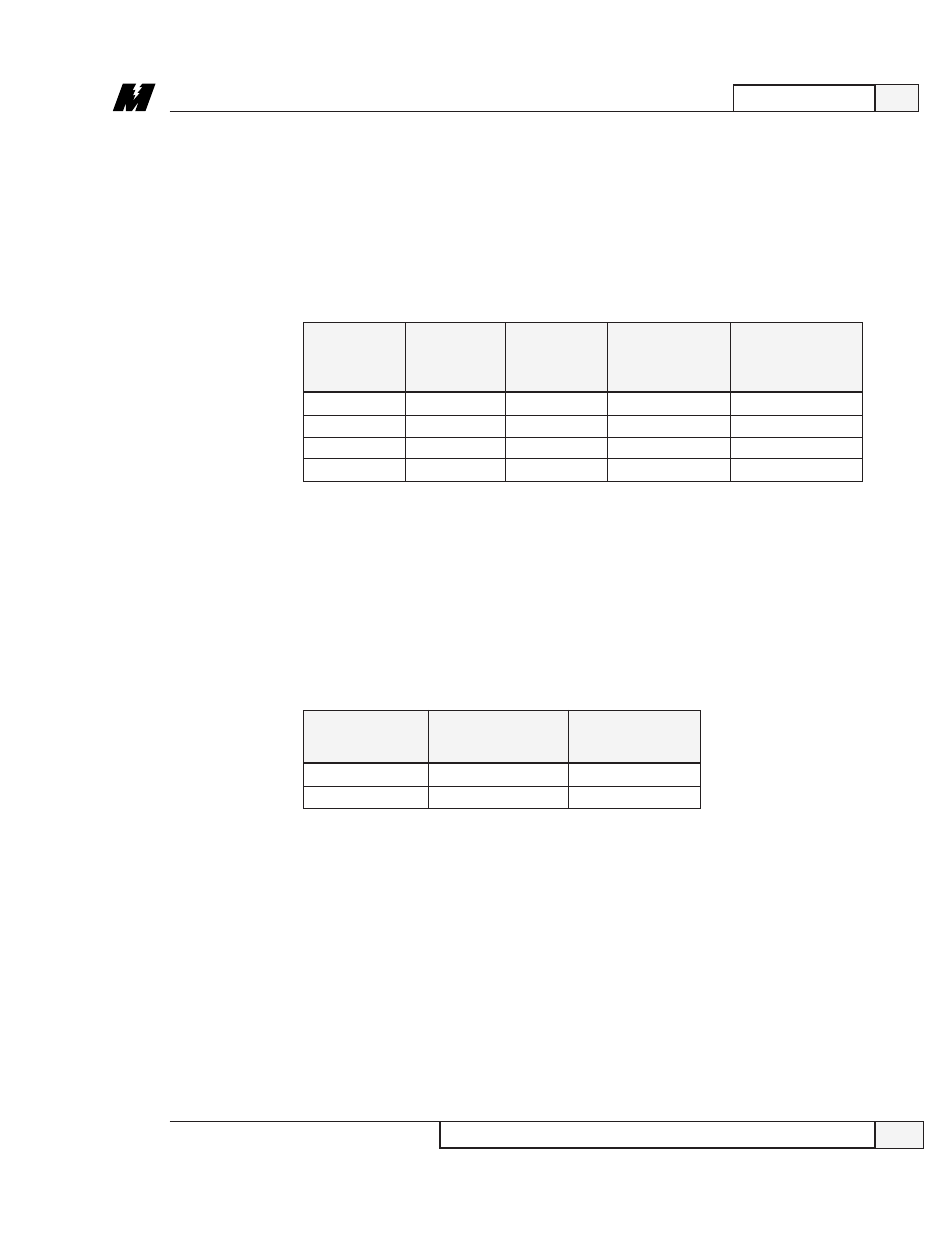
SN-09 Settings
SN-09 is set to match the input voltage and the inverter carrier frequency as
follows:
SN-09
230/460
200/400
LOW
HIGH
VAC
VAC
CARRIER
CARRIER
FREQUENCY
FREQUENCY
0000
X
X
0001
X
X
1000
X
X
1001
X
X
If set for high carrier frequency (low noise operation), the continuous current
rating of the VCD 723 is reduced by 20%. The VCD 723 overload curve is
automatically changed.
SN-12 Settings
SN-12 determines the reaction of the drive to the status of the contact connected
to terminal 3 of the VCD 723. Terminal 3 is always the external fault input and
normally would be used as an E-stop input. In the following table, “N.O.” means
the contact closes on a fault:
SN-12
N.O.
N.C.
CONTACT
CONTACT
0100
X
0101
X
SN-15, 16, 17 & 18 Settings
SN-15 thru SN-18 are set to15 decimal (of hex). This determines that the logic
input terminals 5 thru 8 are read by the DCU only. In other words, they have no
direct effect on the inverter.
SN-20, 21, 22, 23 & 24 Settings
SN-20 thru SN-24 are set to 15 decimal (of hex). This configures the normally
open relay contact (terminals 9 & 10) and the four open collector outputs
(terminals 25, 26, 28 & 29) for control by the DCU.
SN-30 Settings
SN-30 is set for 0100 and should not be changed. This configures the VCD 723
for the torque control mode rather than the speed control mode.