Appendix 3. supplemental description – Yaskawa MP2000 Series User Manual
Page 42
Page
42
TM.MP2000.02, 1/18/2011
Data subject to change without notice
Yaskawa America, Inc.
Á
Appendix 3. Supplemental Description
Appendix 3.1 Assignment Points
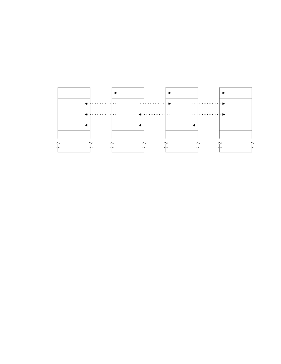
In PCLINK link transmission, the link data received by the counterpart station is stored in a set location according to
the link map address where the transmission data is included because the link map address and size are included in
the transmission data of each station. Therefore, the link maps are the same for all the stations (Figure F3.1.1). The
figure is an example link map of each station in a situation where the link register outputs of each of stations 1~4 have
been assigned with 128 words.
Figure F3.1.1 Link Map of Each Station
When I/O registers (I registers, O registers) are used in link transmission by MP, the lead number used will change
according to the module configuration definition. Even in that case, the counterpart address from the lead is the same
as the link maps of the other stations. (If the I/O lead address is 400H in the module configuration definition, R0001 of
the GL corresponds to IW (OW) 0400 of the MP.)
Even in cases where input data assignment is performed from the link assignment screen, the link assignment will
be performed together with the output side data address. (It is not possible to change the register numbers as desired
on the input side. It is necessary to assign an MP-side input register counterpart address.)
Output
MP2XXX
PCLINK
Output
GL120
PCLINK
Output
MP2XXX
PCLINK
Output
GL60
PCLINK
Station 1
Station 2
Station 3
Station 4
R10001
OW0000
IW0400
R0001
IW0080
IW0480
IW0100
IW0180
OW0500
IW0580
R10129
R10257
R10385
R0129
R0257
R0385
Map when I/O lead address is 0000.
Map when the I/O lead address is 0400