Irritrol PCW Control User Manual
Page 6
4
PCW Control
S
Installation
run time duration assigned to each zone.
• Any number of schedules can be defined and saved
to memory for later recall, however every schedule
must have a unique name assignment.
13. Select the Default Schedule option to open the
new schedule with a run time Blank Schedule to
start without presets.
14. Click the Finish Button.
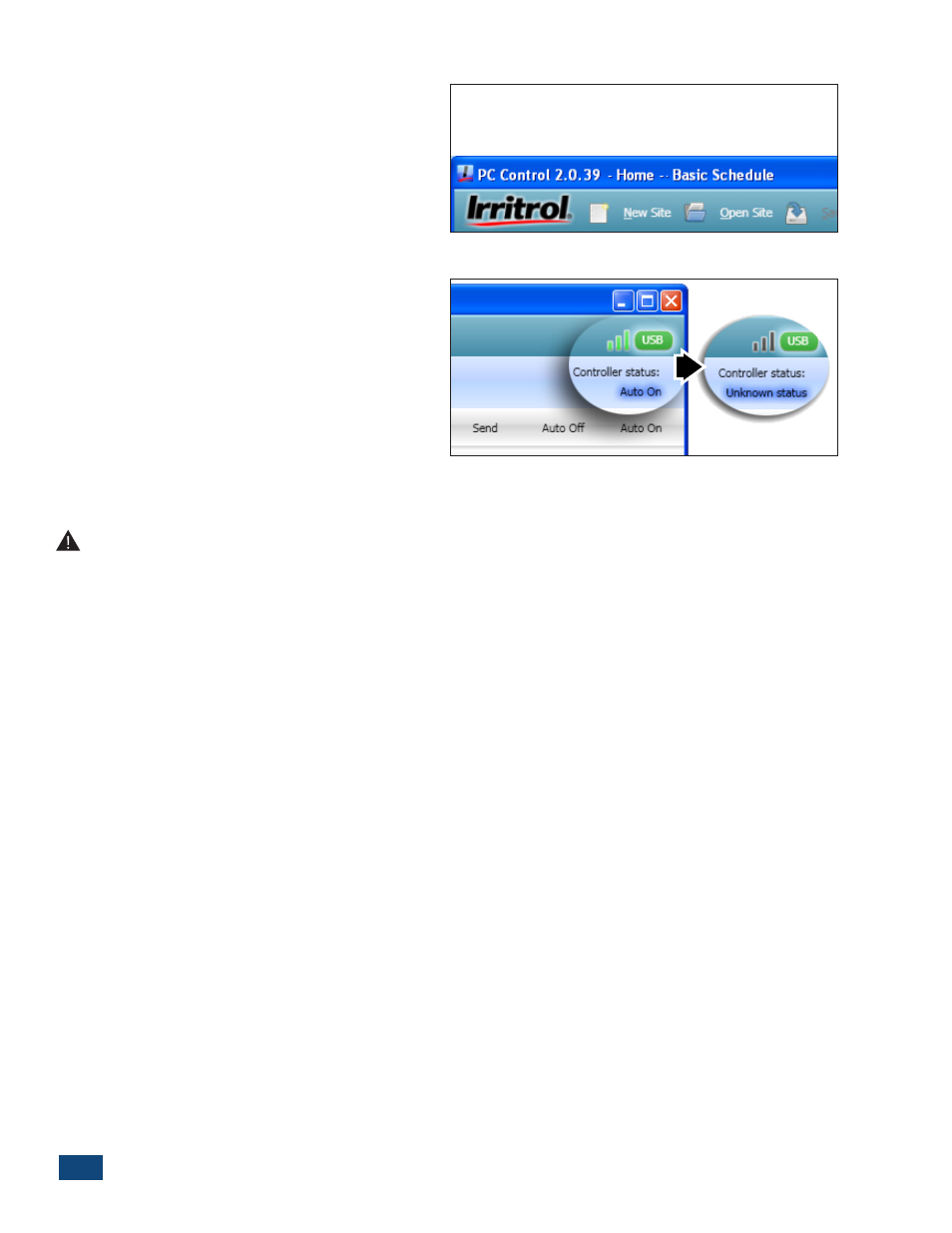
• The site and schedule name will be displayed at
the top of the program window (Figure 1.5).
The PCW Control program should begin communicat-
ing with the Controller(s) at this time and will activate
the control system; indicated by green signal bars and
the Auto On controller status. If a communication link
is not established, Unknown Status will be displayed.
(Figure 1.6) This condition is usually caused by a
mismatching PIN. Verify the PC-R and Controller have
a matching PIN and the Controller(s) can be operated
manually with the PC-R.
Change PIN
Important PIN Information: As a security measure, the PC-Remote (PC-R) and Controller utilize a
four-digit PIN code to enable wireless communication. Both units are initially set to 0000 by default. This
is an optional feature and can remain 0000 if desired. If you wish to change the PIN to prevent unintended
system operation, read this section.
Changing the system’s PIN can only be done from the computer when all the PINs are the same to begin with.
The parts of the system, computer, PC-R, and Controller all have to be communicating for “Change PIN” to
function. In the case of mismatched PINs (and in the case of multiple Controllers in the system), the PIN and
controller number need to be set manually in each controller. See the procedure below:
1. On the front of the Controller, press the “MANUAL” and “AUTO ON” buttons simultaneously to start the
“POWER” light blinking and illuminate one of the station lights.
2. With the station lights 1 thru 9 representing PIN digits 1-9 and with 10 representing “0”, use the “MANUAL”
button to advance to and illuminate the first digit desired for the PIN.
3. Press “AUTO ON” to move the light down from “POWER” to illuminate “SIGNAL”. The “SIGNAL” light represents
the second PIN digit. Again, use the “MANUAL” button to move to and illuminate the second, desired PIN
number and then press “AUTO ON”.
4. Repeat the above steps to set the third and fourth PIN digits with “SENSOR” and “MASTER VALVE / PUMP”
illuminated respectively.
5. The last digit, represented by the “TEST” light, is for the controller or Controller number. If there is only one
controller in the system, set or leave the controller number at “1”. If setting up a second controller for the
system, use the “MANUAL” button to move to #2 in the “STATION” lights. The controller number selection
only goes up to four.
6. Hold down the “AUTO ON” button until the lights start a sequential display and then release the button. The
Controller will demonstrate what was set for each of the four PIN numbers and the controller number and
will then return to AUTO mode on its own.
Figure 1.5
Figure 1.6