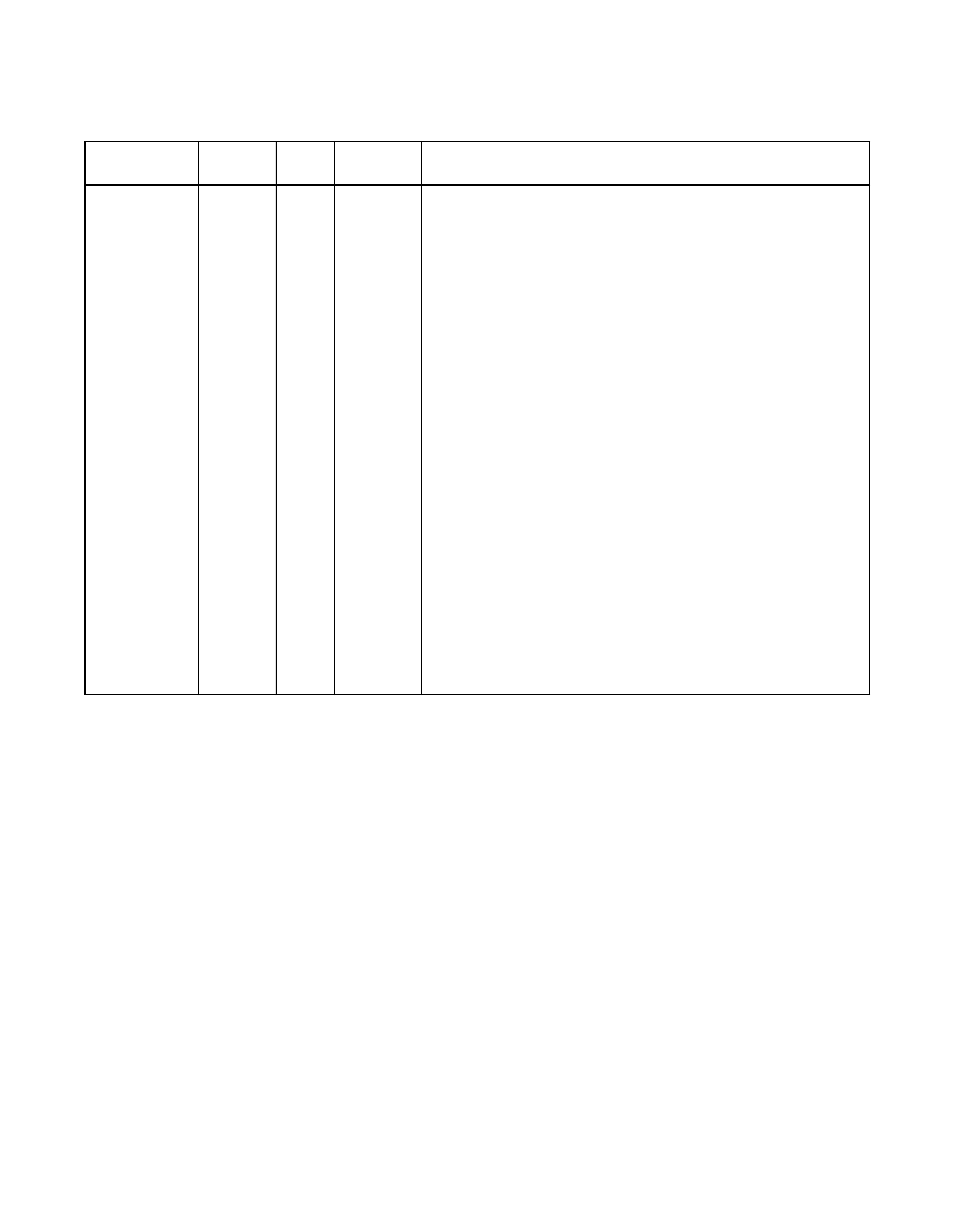
Table 3.10 scsi function a control signals, Scsi function a control signals – Avago Technologies LSI53C1010R User Manual
Page 106
3-12
Signal Descriptions
Version 2.2
Copyright © 2000–2003 by LSI Logic Corporation. All rights reserved.
Table 3.10
SCSI Function A Control Signals
Name
1
1. LVD Mode: The negative and positive halves of the LVDlink signal pairs are shown for SCSI Function
A Control. SE Mode: The SCSI Function A Control signals are shown. All positive (+) signals are
at 0 V.
Bump
Type
Strength
Description
A_SCD
−
A_SCD+
A_SIO
−
A_SIO+
A_SMSG
−
A_SMSG+
A_SREQ
−
A_SREQ+
A_SACK
−
A_SACK+
A_SBSY
−
A_SBSY+
A_SATN
−
A_SATN+
A_SRST
−
A_SRST+
A_SSEL
−
A_SSEL+
K3
K4
K5
J5
L2
L1
J2
J3
M5
L5
N3
N4
M4
N5
M1
M2
L4
K2
I/O
SE:
48 mA
SCSI
LVD:
12 mA
UniLVD
SCSI phase line, command/data.
SCSI phase line, input/output.
SCSI phase line, message.
Data handshake line from target device.
Data handshake signal from the initiator device.
SCSI bus arbitration signal, busy.
SCSI Attention, the initiator is requesting a message out
phase.
SCSI bus reset.
SCSI bus arbitration signal, select device.