PLANET GS-4210-24P2S User Manual
Page 342
Advertising
User’s Manual of GS-4210-24P2S
342
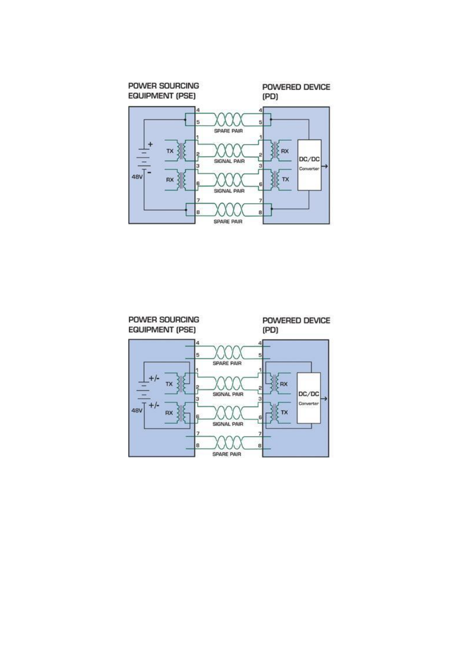
pair on pins 7 and 8 connected and forming the negative supply. (In fact, a late change to the spec allows either polarity to be
used).
Figure 8-1:
Power Supplied over the Spare Pins
The data pairs are used. Since Ethernet pairs are transformer coupled at each end, it is possible to apply DC power to the
center tap of the isolation transformer without upsetting the data transfer. In this mode of operation the pair on pins 3 and 6 and
the pair on pins 1 and 2 can be of either polarity.
Figure 8-2:
Power Supplied over the Data Pins
Advertising
See also other documents in the category PLANET Routers:
- FNSW-1601 (2 pages)
- FNSW-1601 (2 pages)
- FGSW-1816HPS (2 pages)
- FGSW-1816HPS (110 pages)
- FGSW-1816HPS (105 pages)
- WGSD-10020HP (16 pages)
- GS-5220-16S8CR (432 pages)
- FGSD-1022P (226 pages)
- FGSD-1022P (12 pages)
- FGSD-910P (28 pages)
- FGSW-1602RS (30 pages)
- FGSW-2402S (39 pages)
- FGSW-2620PVS (50 pages)
- FGSW-2624SF (2 pages)
- FGSW-2620VM (213 pages)
- FGSW-2620VM (2 pages)
- FGSW-2624SF (2 pages)
- FGSW-2620VM (96 pages)
- FGSW-2620 (2 pages)
- FGSW-2620CS (2 pages)
- FGSW-2620CS (80 pages)
- FGSW-2620CS (2 pages)
- FGSW-2620CS (81 pages)
- FGSW-2840 (2 pages)
- FGSW-4840S (263 pages)
- FGSW-4840S (2 pages)
- FGSW-4840S (38 pages)
- FNSW-1600P (20 pages)
- FNSW-1600S (33 pages)
- FNSW-2400PS (2 pages)
- FNSW-2400PS (70 pages)
- FNSW-1602S (43 pages)
- FNSW-2402S (39 pages)
- FNSW-4800 (2 pages)
- FNSW-2401CS (38 pages)
- FSD-1604 (12 pages)
- FSD-2405 (18 pages)
- FSD-1606 (2 pages)
- FSD-803 (2 pages)
- FSD-803 (2 pages)
- FSD-504HP (2 pages)
- FSD-805ST (20 pages)
- FSD-804P (21 pages)
- FSD-808P (20 pages)
- FSD-808P (22 pages)