3 switch rear panel, 2 installing the switch, 1 desktop installation – PLANET LRP-822CS User Manual
Page 25
User’s Manual of LRP-822CS
25
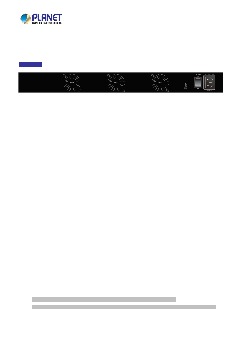
2.1.3 Switch Rear Panel
The rear panel of the LRP Managed Switch indicates an AC inlet power socket, which accepts input power from 100 to 240V AC,
50-60Hz.
Figure 2-1-3
shows the rear panel of these LRP Managed Switches
Rear Panel
Figure 2-1-3 Rear Panel of LRP-822CS
■
AC Power Receptacle
For compatibility with electric service in most areas of the world, the LRP Managed Switch’s power supply automatically
adjusts to line power in the range of 100-240V AC and 50/60 Hz.
Plug the female end of the power cord firmly into the receptalbe on the rear panel of the LRP Managed Switch. Plug the
other end of the power cord into an electrical outlet and the power will be ready.
Power Notice:
The device is a power-required device, which means it will not work till it is powered. If your networks
should be active all the time, please consider using UPS (Uninterrupted Power Supply) for your device.
It will prevent you from network data loss or network downtime.
Power Notice:
In some areas, installing a surge suppression device may also help to protect your LRP Managed
Switch from being damaged by unregulated surge or current to the LRP Managed Switch.
2.2 Installing the Switch
This section describes how to install your LRP Managed Switch and make connections to the LRP Managed Switch. Please
read the following topics and perform the procedures in the order being presented. To install your LRP Managed Switch on a
desktop or shelf, simply complete the following steps.
2.2.1 Desktop Installation
To install the LRP Managed Switch on desktop or shelf, please follow these steps:
Step 1:
Attach the rubber feet to the recessed areas on the bottom of the LRP Managed Switch.
Step 2:
Place the LRP Managed Switch on the desktop or the shelf near an AC power source, as shown in
Figure 2-1-4
.