2 rack mounting – PLANET LRP-822CS User Manual
Page 26
User’s Manual of LRP-822CS
26
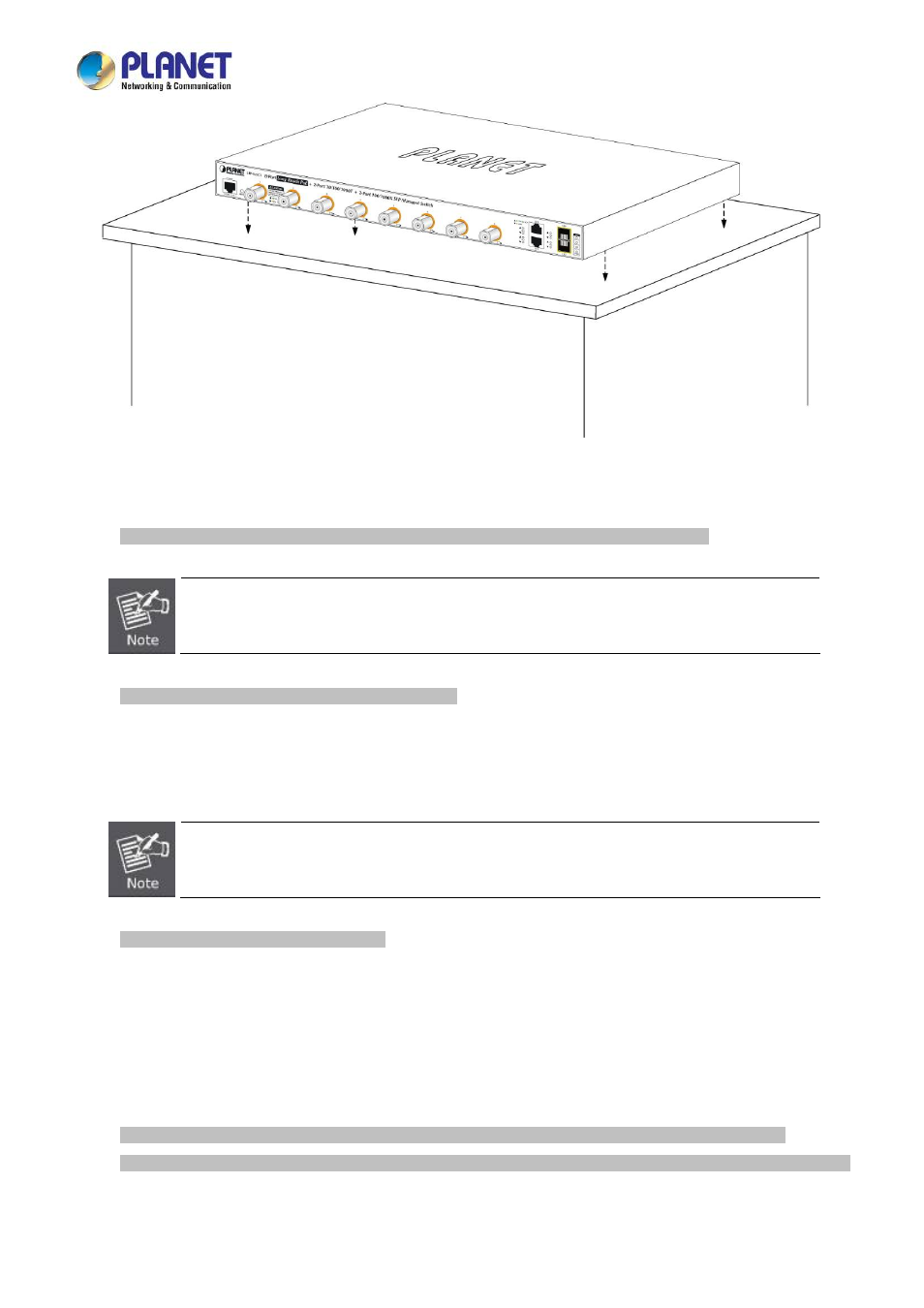
Figure 2-1-4 Place the LRP Managed Switch on the desktop
Step 3:
Keep enough ventilation space between the LRP Managed Switch and the surrounding objects.
When choosing a location, please keep in mind the environmental restrictions discussed in Chapter 1,
Section 4 under specifications.
Step 4:
Connect the LRP Managed Switch to network devices.
Connect one end of a standard network cable to the 10/100/1000 RJ45 ports and standard coaxial cable to LRP ports on
the front of the LRP Managed Switch
.
Connect the other end of the cable to the network devices such as printer server,
workstation or router.
Connection to the LRP Managed Switch requires UTP Category 5 network cabling with RJ45 tips. For
more information, please see the Cabling Specification in Appendix A.
Step 5:
Supply power to the LRP Managed Switch.
Connect one end of the power cable to the LRP Managed Switch. Connect the power plug of the power cable to a
standard wall outlet. When the LRP Managed Switch receives power, the Power LED should remain solid Green.
2.2.2 Rack Mounting
To install the LRP Managed Switch in a 19-inch standard rack, please follow the instructions described below.
Step 1:
Place the LRP Managed Switch on a hard flat surface, with the front panel positioned towards the front side.
Step 2:
Attach the rack-mount bracket to each side of the LRP Managed Switch with supplied screws attached to the package.
Figure 2-1-5
shows how to attach brackets to one side of the LRP Managed Switch.