14 mvr – PLANET XGSW-28040 User Manual
Page 173
User’s Manual of XGSW-28040
VLAN ID
VLAN ID of the group.
Group
Group address of the group displayed.
Port
Switch port number.
Mode
Indicates the filtering mode maintained per (VLAN ID, port number, Group
Address) basis. It can be either Include or Exclude.
Source Address
IP Address of the source. Currently, system limits the total number of IP source
addresses for filtering to be 128.
Type
Indicates the Type. It can be either Allow or Deny.
Hardware Filter/Switch
Indicates whether data plane destined to the specific group address from the
source IPv6 address could be handled by chip or not.
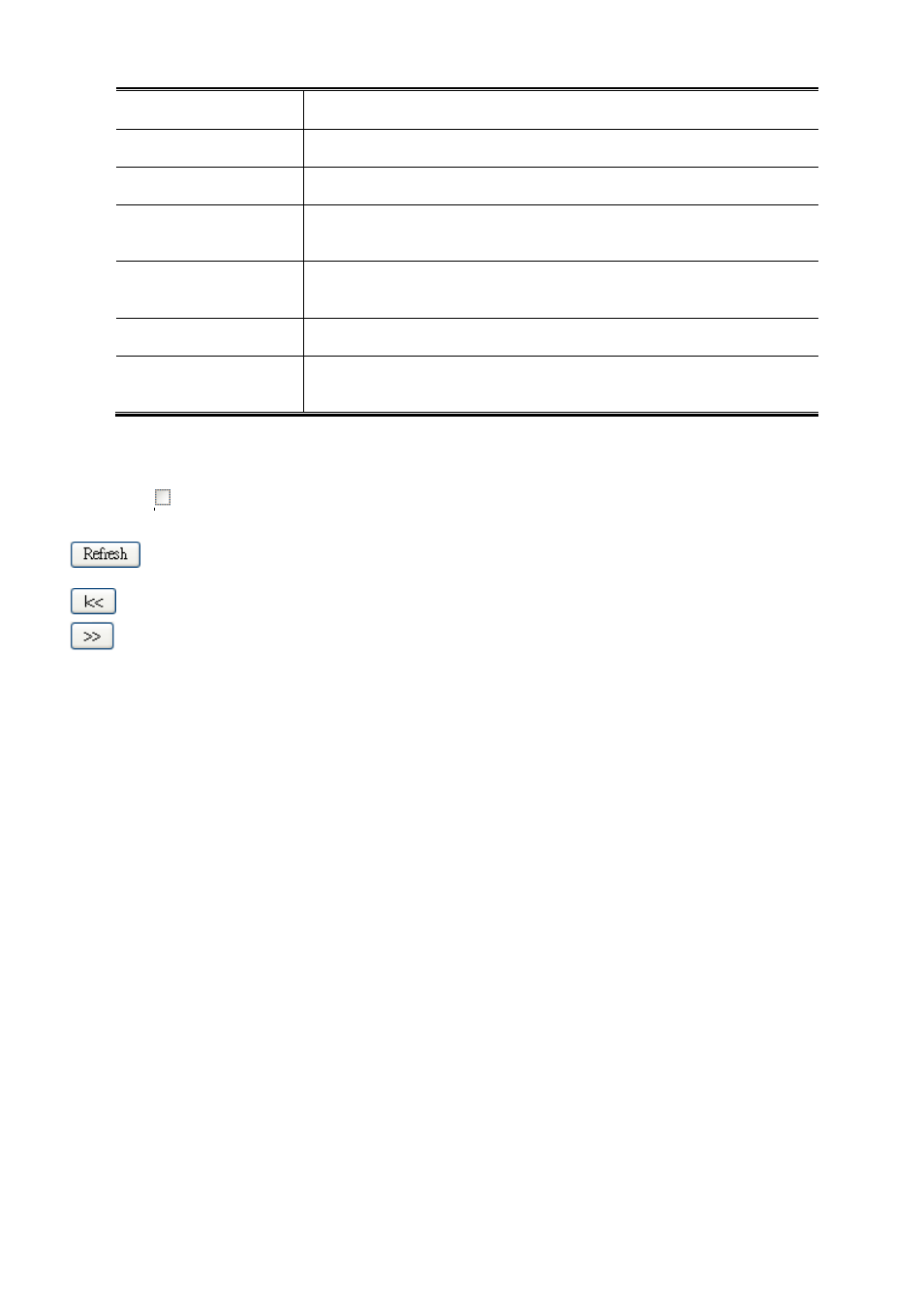
Buttons
Auto-refresh
: Automatic refresh occurs every 3 seconds.
: Refreshes the displayed table starting from the input fields.
: Updates the table starting from the first entry in the MLD SFM Information Table.
: Updates the table, starting with the entry after the last entry currently displayed.
4.8.14 MVR
The MVR feature enables multicast traffic forwarding on the Multicast VLANs. In a multicast television application, a PC or a
network television or a set-top box can receive the multicast stream. Multiple set-top boxes or PCs can be connected to one
subscriber port, which is a switch port configured as an MVR receiver port. When a subscriber selects a channel, the set-top box
or PC sends an IGMP/MLD report message to Switch A to join the appropriate multicast group address. Uplink ports that send
and receive multicast data to and from the multicast VLAN are called MVR source ports. It is allowed to create at maximun 8
MVR VLANs with corresponding channel settings for each Multicast VLAN. There will be totally at maximun 256 group
addresses for channel settings.
This page provides MVR related configuration. The MVR screen in
Figure 4-8-17
appears.
173