Cable connections, Cable, Connections – ProSoft Technology MVI69-DNP User Manual
Page 89
Reference MVI69-DNP
♦ CompactLogix or MicroLogix Platform
DNP 3.0 Master/Slave Communication Module
ProSoft Technology, Inc.
Page 89 of 129
November 3, 2008
Step Description
1
The Master driver obtains configuration data from the configuration file. The configuration
data obtained includes the Master Slave and Command Lists. These values are used by
the Master driver to determine the type of commands to be issued to other nodes on the
DNP network.
2
After configuration, the Master driver begins transmitting read and/or write commands to
the other nodes on the network. If writing data to another node, the data for the write
command is obtained from the module's internal database to build the command.
3
Presuming successful processing by the node specified in the command, a response
message is received into the Master driver for processing.
4
Data received from the node on the network is passed into the module's internal
database, assuming a read command.
5
Status data is returned to the CompactLogix processor for each command in the Master
Command List.
Refer to the Installing and Configuring the Module section for a complete
description of the parameters required to define the virtual DNP Master port.
5.3 Cable
Connections
The application ports on the MVI69-DNP module support RS-232, RS-422, and
RS-485 interfaces. Please inspect the module to ensure that the jumpers are set
correctly to correspond with the type of interface you are using.
Note: When using RS-232 with radio modem applications, some radios or modems require
hardware handshaking (control and monitoring of modem signal lines). Enable this in the
configuration of the module by setting the UseCTS parameter to 1.
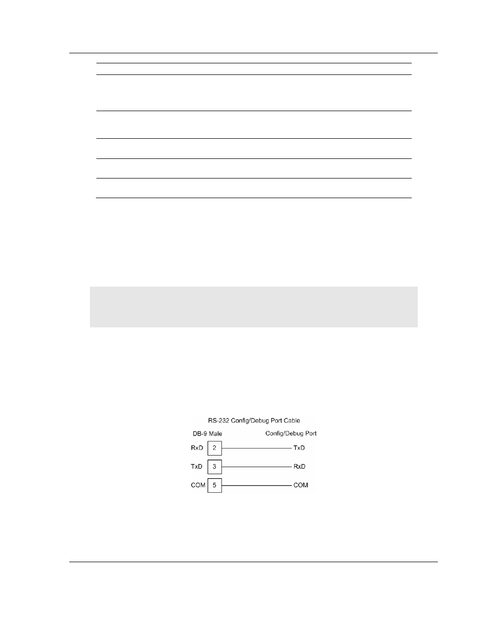
5.3.1 RS-232
Configuration/Debug Port
This port is physically an RJ45 connection. An RJ45 to DB-9 adapter cable is
included with the module. This port permits a PC based terminal emulation
program to view configuration and status data in the module and to control the
module. The cable for communications on this port is shown in the following
diagram: