Altera FIR Compiler User Manual
Page 36
3–12
Chapter 3: Parameter Settings
Specify the Architecture Specification
© May 2011
Altera Corporation
describe the FIR Compiler options that
are available for each architecture.
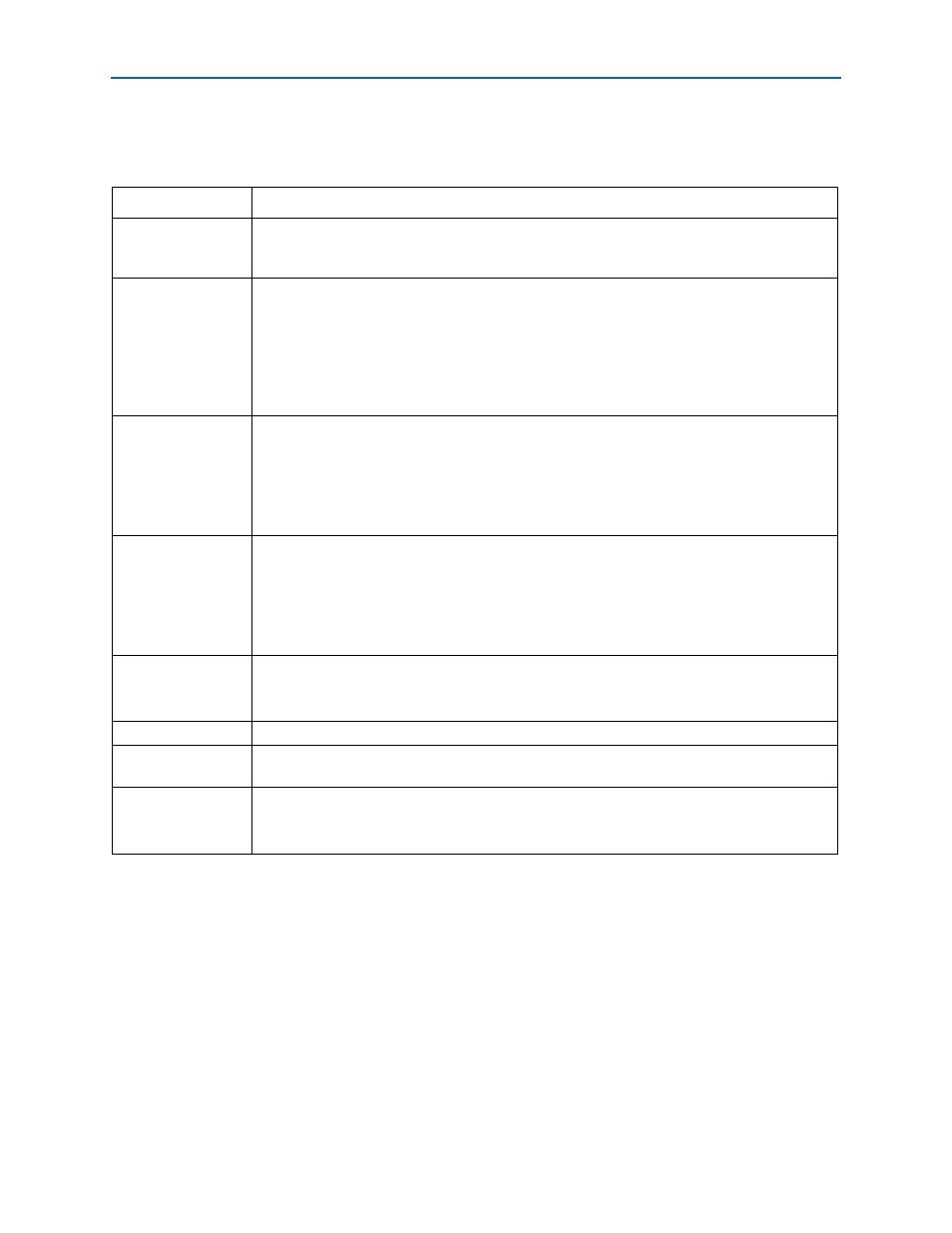
Table 3–4. Multicycle Filter Architecture
Parameter
Description
Clocks to Compute
Specifies the number of clock cycles required to compute a result. Using more clock cycles to
compute a result reduces the filter resource usage. The number of multipliers the filter uses is equal
to the number of taps divided by the number of clock cycles to compute the result.
Data Storage
Specifies the device resources used for data storage. You can select Logic Cells, M512, M4K,
M-RAM, MLAB, M9K, M144K, or Auto. If you select Auto, the Quartus II software may store data in
logic cells or memory, depending on the resources in the selected device, the size of the data
storage, the number of clock cycles to compute a result, and the number of input channels.
The option list changes depending on which device you select and the number of clock cycles to
compute a result. Choosing embedded memory reduces logic cell usage and may increase the
speed of the filter.
Coefficient Storage
Specifies the device resources used for coefficient storage. You can select Logic Cells, M512, M4K,
MLAB, M9K, or Auto. If you select Auto, the Quartus II software automatically selects the most
appropriate memory block size for the selected device.
The option list changes depending on which device you select and the number of clock cycles to
compute a result. Choosing embedded memory reduces logic cell usage and may increase the
speed of the filter.
Multiplier
Implementation
Specify the device resources used to implement the multiplier. You can select Logic Cells, DSP
Blocks, or Auto. If you select Auto, the Quartus II software turns on the DSP Block Balancing logic
option.
Using embedded DSP blocks results in a smaller and faster design in a device with enough DSP
blocks for all multipliers. The most efficient use of DSP block is for 9×9 (in groups of 8) or 18×18
(in groups of 4) multipliers.
Force Non-Symmetric
Structure
If you want to create a design that uses both symmetric and non-symmetric coefficients, turn on
this option.
Non-symmetric architectures may use more resources.
Coefficients Reload
Turn on this option to allow coefficient reloading.
Pipeline Level
When you turn on this option, FIR Compiler creates a higher performance filter that uses more
device resources.
Use Single Clock
Use this option when creating designs with DSP Builder. This option is only available when
Coefficients Reload is on and M512, M4K, MLAB or M9K is specified in Coefficient Storage.
This option ties the
coef_clk_in
and
clk
signals together.
Note to
(1) When the input data is unsigned, the input data bit width should be greater than or equal to one. When the input data is signed, the input data
bit width should be greater than or equal to two.