Altera FIR Compiler User Manual
Page 52
4–10
Chapter 4: Functional Description
FIR Compiler
© May 2011
Altera Corporation
Because the FIR Compiler is an automated design tool, it is possible to implement a
multichannel, multiple coefficient set interpolation or decimation filter (which is
further implemented as a multichannel, multiple coefficient set structure).
The net result of these optimization techniques is a general savings in resources.
Implementation Details for Interpolation and Decimation Structures
illustrate the results when applying polyphase decomposition to
interpolation and decimation filters.
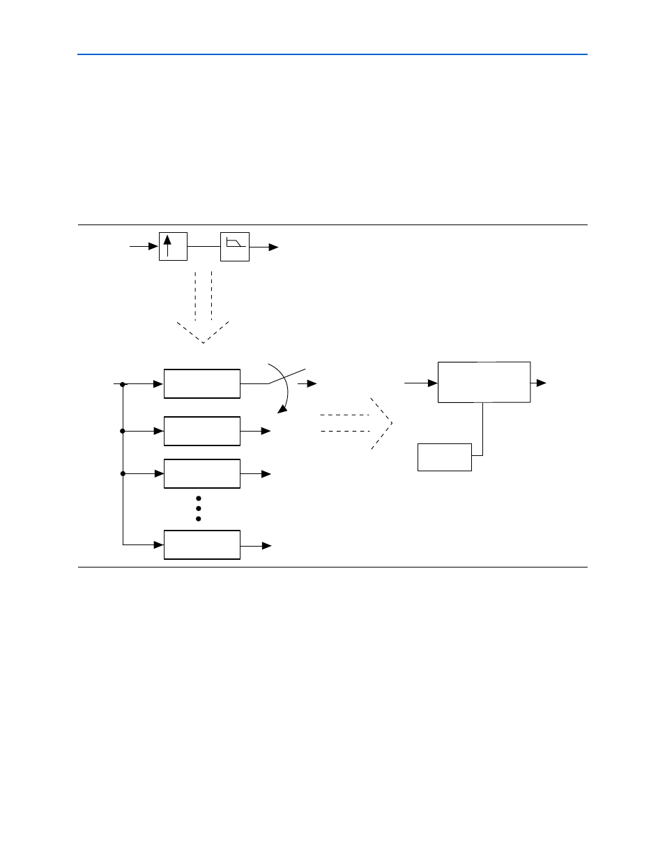
illustrates an interpolation structure. It takes a constant number of clocks
to compute each polyphase output. The input data must be held for the number of
clocks to compute each polyphase output multiplied by the number of polyphase
units (which is the same as the interpolation factor).
shows a decimation filter (with polyphase decomposition).
Each polyphase filter must be computed prior to computing the final results. Because
there are several polyphase results that must be accumulated, it is clear that the
output will update every N clocks, where N = number of polyphase filters × number
of clocks to compute each polyphase result.
1
The number of polyphase filters is equal to the decimation factor. The input data must
be held for the time it takes to compute a single polyphase filter.
Figure 4–9. Interpolation Filter Structure
P(0)
P(1)
P(2)
P(N-1)
input
output
input
LPF
output
N
input
N Channel
N Coefficient Set
Single Rate FIR Filter
Control
Circuitry
output