Setup elements, Setup elements –17 – Altera Stratix IV E FPGA Development Board User Manual
Page 25
Chapter 2: Board Components
2–17
Configuration, Status, and Setup Elements
May 2011
Altera Corporation
Stratix IV E FPGA Development Board Reference Manual
lists the board-specific LEDs component references and manufacturing
information.
Setup Elements
The development board includes several different kinds of setup elements. This
section describes the following setup elements:
■
MAX II DIP switch
■
User DIP switch
■
Clock enable DIP switch
■
JTAG chain jumpers
■
On-Board memory headers
■
Reset configuration push-button switch
■
Rotary switch
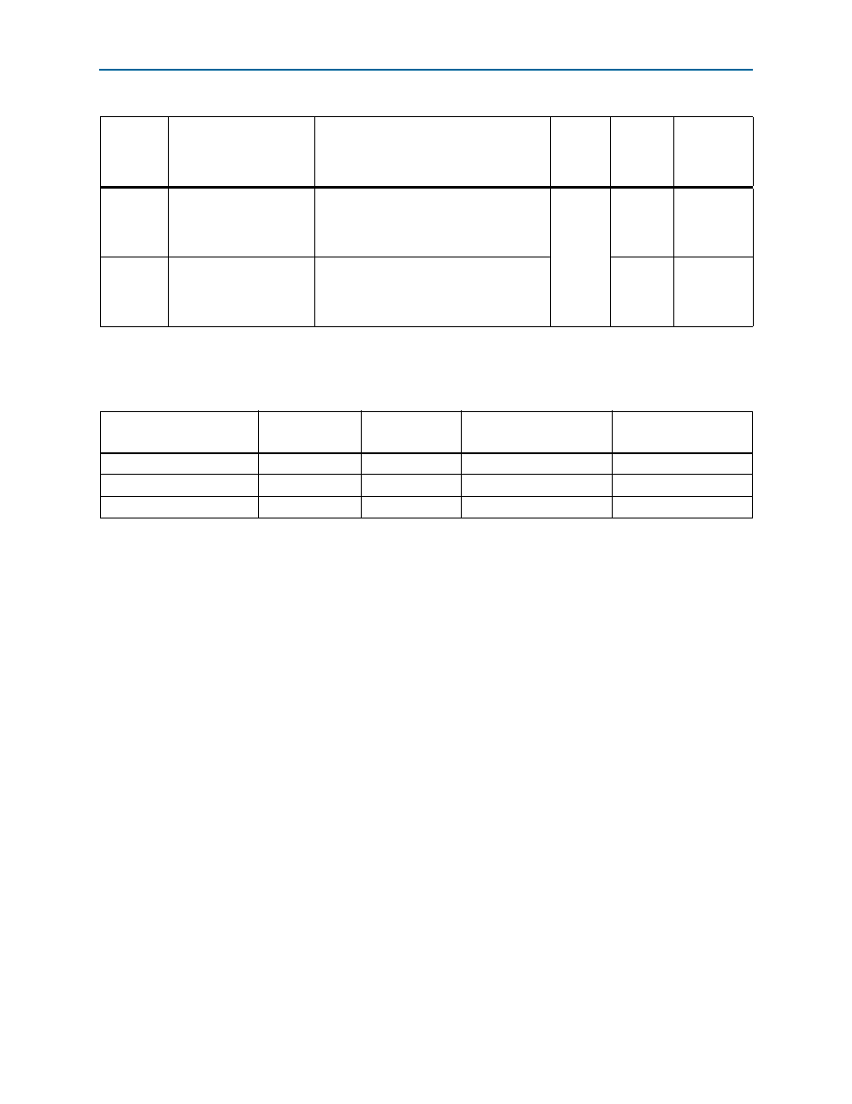
D16
HSMA_PSNTn
Green LEDs. Illuminates when HSMC port
A has a board or cable plugged-in such that
pin 160 becomes grounded. Driven by the
add-in card.
2.5-V
—
—
D5
HSMB_PSNTn
Green LEDs. Illuminates when HSMC port
B has a board or cable plugged-in such that
pin 160 becomes grounded. Driven by the
add-in card.
—
—
Table 2–8. Board-Specific LEDs (Part 2 of 2)
Board
Reference
Schematic Signal Name
Description
I/O
Standard
Stratix IV
E Device
Pin
Number
Other
Connections
Table 2–9. Board-Specific LEDs Component References and Manufacturing Information
Board Reference
Description
Manufacturer
Manufacturer
Part Number
Manufacturer Website
D5, D7-D19, D22-D30
Green LEDs
Lumex Inc.
SML-LX1206GC-TR
D20
Red LED
Lumex Inc.
SML-LX1206IC-TR
D21
Blue LED
Lumex Inc.
SML-LX1206USBC-TR