Max ii dip switch, Max ii dip switch –18 – Altera Stratix IV E FPGA Development Board User Manual
Page 26
2–18
Chapter 2: Board Components
Configuration, Status, and Setup Elements
Stratix IV E FPGA Development Board Reference Manual
May 2011
Altera Corporation
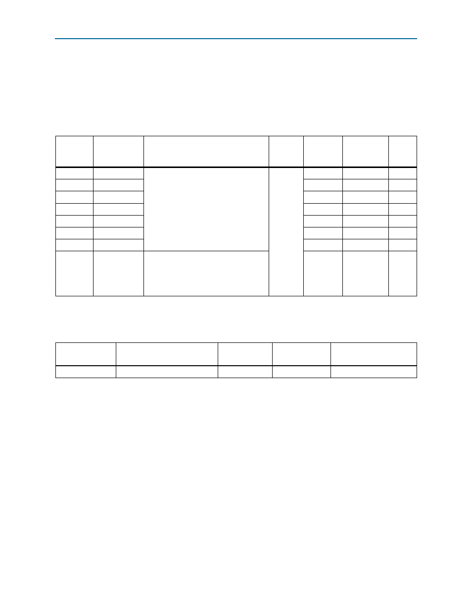
MAX II DIP Switch
The MAX II DIP switch (SW2) provides user-specific control settings for the MAX
II
CPLD EPM2210 System Controller logic design. There is a 66-MHz clock select switch
which is used to select between the on-board oscillator or the user-defined external
clock source supplied on the SMA inputs.
shows the switch controls and
descriptions.
lists the MAX II DIP switch component reference and manufacturing
information.
Table 2–10. MAX II DIP Switch Controls
Board
Reference
Schematic
Signal Name
Description
I/O
Standard
Stratix IV E
Device Pin
Number
Other
Connections
Default
SW2.1
DIP0
MAX II user-defined DIP switch. When
the switch is in the OPEN or OFF position,
a logic 1 is selected. When the switch is
in the CLOSED or ON position, a logic 0
is selected.
2.5-V
—
U10.E14
ON
SW2.2
DIP1
—
U10.D13
ON
SW2.3
DIP2
—
U10.K16
ON
SW2.4
DIP3
—
U10.N2
ON
SW2.5
DIP4
—
U10.N14
ON
SW2.6
DIP5
—
U10.M13
ON
SW2.7
DIP6
—
U10.N15
ON
SW2.8
CLK66_SEL
Selects either the on-board oscillator or
the SMA inputs.
ON : SMA input clock select
OFF : 66 MHz clock select
—
U10.L14
ON
Table 2–11. MAX II DIP Switch Component Reference and Manufacturing Information
Board Reference
Description
Manufacturer
Manufacturer
Part Number
Manufacturer Website
SW2
Eight-Position slide DIP switch
Grayhill
76SB08ST