Altera Cyclone IV GX FPGA Development Board User Manual
Page 21
Chapter 2: Board Components
2–13
Configuration, Status, and Setup Elements
May 2013
Altera Corporation
Cyclone IV GX FPGA Development Board
Reference Manual
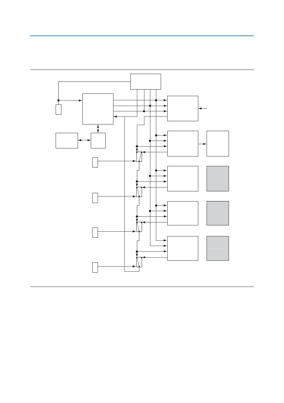
The embedded USB-Blaster is automatically disabled when an external USB-Blaster is
connected to the JTAG chain.
illustrates the JTAG chain.
The Cyclone IV GX FPGA is configured via JTAG using the MAX II configuration
controller design (embedded blaster) as the primary configuration mode. The board
includes a MAX II CPLD EPM2210 System Controller which interfaces directly to the
Cyclone IV GX FPGA for configuration, LCD control, power monitor control, and
other purposes. The MAX II CPLD EPM2210 System Controller contains the required
state machine and control logic to determine the configuration source for the Cyclone
IV GX FPGA.
Figure 2–4. JTAG Chain
Embedded
Blaster
GPIO
TCK
EP4CGX150
FPGA
Analog
Switch
EPM2210
System
Controller
HSMC
Port A
HSMC
Port B
GPIO
TMS
GPIO
TDO
GPIO
TDI
JTAG Master
GPIO
DISABLED
JTAG Master/Slave
JTAG Master/Slave
Installed
HSMC
Card
Installed
HSMC
Card
TCK
TMS
TDI
TDO
TCK
TMS
TDI
TDO
TCK
TMS
TDI
TDO
TCK
TMS
TDI
TDO
JTAG Slave
JTAG Slave
Analog
Switch
Analog
Switch
EPM2210_JTAG_EN
HSMA_JTAG_EN
HSMB_JTAG_EN
ALWAYS
ENABLED
(in chain)
SW5.1
SW5.2
SW5.3
SW5
10-pin
JTAG Header
Flash
Memory
(on install)
PCI Express
Edge
Connector
JTAG Master/Slave
PCI Express
Motherboard
TCK
TMS
TDI
TDO
Analog
Switch
PCIE_JTAG_EN
SW5.4
Embedded
Blaster
Connection
USB
PHY
J4
J6