Pcie control dip switch, Configuration settings – Altera Cyclone IV GX FPGA Development Board User Manual
Page 27
Chapter 2: Board Components
2–19
Configuration, Status, and Setup Elements
May 2013
Altera Corporation
Cyclone IV GX FPGA Development Board
Reference Manual
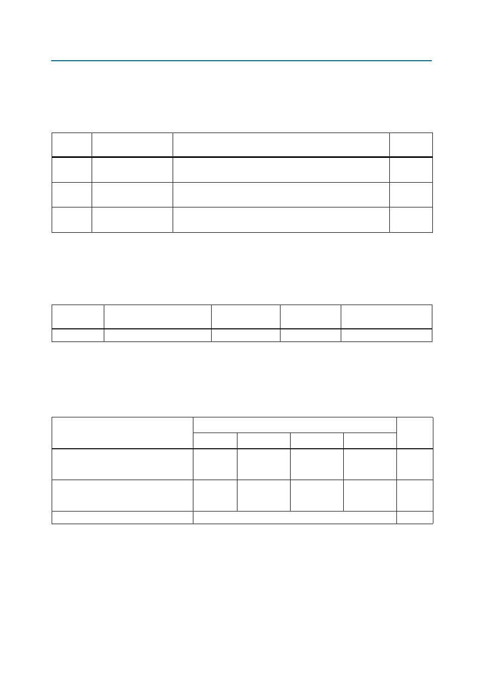
PCIe Control DIP Switch
The PCIe control DIP switch (SW4) is provided to enable or disable the different
configurations.
shows the switch controls and descriptions.
lists the PCIe control DIP switch component reference and manufacturing
information.
Configuration Settings
The MAX
II CPLD EPM2210 System Controller controls the configuration settings. A
configuration scheme is selected by driving the MSEL pins either high or low, as
shown in
.
Table 2–14. PCIe Control DIP Switch Controls
Board
Reference
Schematic Signal Name
Description
Default
SW4.1
PCIE_PRSNT2n_x1
ON : Enable x1 presence detect
OFF : Disable x1 presence detect
ON
SW4.2
PCIE_PRSNT2n_x4
ON : Enable x4 presence detect
OFF : Disable x4 presence detect
ON
SW4.4
USB_DISABLE
ON : Embedded USB-Blaster disabled
OFF : Embedded USB-Blaster enabled
OFF
Note to
:
(1) ON indicates a setting of ’0’ while OFF indicates a setting of ’1’.
Table 2–15. PCIe Control DIP Switch Component Reference and Manufacturing Information
Board
Reference
Description
Manufacturer
Manufacturer
Part Number
Manufacturer Website
SW4
Four-position slide DIP switch
C & K Components
TDA04H0SB1
Table 2–16. Configuration Settings
Configuration Scheme
Setting
POR
Delay
MSEL3
MSEL2
MSEL1
MSEL0
Active Serial—Enables active serial
configuration with fast or standard
power-on-reset delay.
1
1
0
1
Standard
Fast Passive Parallel—Enables FPP
configuration with fast or standard
power-on-reset delay.
0
0
0
1
Standard
JTAG—JTAG-based configuration
X
—
Notes to
:
(1) ON indicates a setting of ’0’ while OFF indicates a setting of ’1’.
(2) X indicates does not care. The JTAG-based configuration takes precedence over other configuration schemes and therefore, the MSEL[] pin
settings are ignored.