Figure 2, Figure 3, Wiring the canopen connector for canopen drives – Applied Motion ST10-C-CE User Manual
Page 10: Canopen bitrate & nodeid, Figure 2: figure 3, Gnd can_l shld can_h
10
920-0025 Rev K
3/5/2015
CANopen User Manual
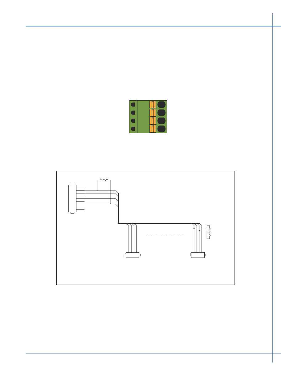
Wiring the CANopen Connector for CANopen Drives
Please refer to Applied Motion Products CANopen Drive Hardware Manual for the Com-
munication connection. As an example, we use the connections for the ST5-C drive.
Applied Motion Products ST5-C drive uses a four-pin spring connector, shown in Figure 2
below, and conforms to CiA303 specification. The connector should be wired in a daisy-chain
configuration, as shown in Figure 3 below, with a 120 ohm resistor used to terminate each end.
Other wiring topologies, such as star networks, are not recommended due to wave reflection
problems. Please reference specific hardware manuals for your drive’s wiring configuration.
Figure 2: The CANopen Connector
Figure 3 shows a CANopen network with two Applied Motion Products ST5-C drive con-
nectors wired to a Kvaser Leaf USB to CANopen Adapter.
Figure 3: Wiring Schematic
CANopen BitRate & NodeID
Applied Motion Products CANopen drives have three settings, one for Bit Rate and two for
Node-ID.
The Bit Rate is configured using an 8-position switch. See Table 1 for the Bit Rate settings.
Please reference the drive’s hardware manual for the location of the Bit Rate switch.
GND
CAN_L
SHLD
CAN_H
1
.1” Spacing Spring Plug
DSUB9 Female
R termination:
Network must be terminated at each
end with a 120 ohm resistor.
n:
Cable may be made with up to 127 drive
connectors. Termination is only required
at each end.
.1” Spacing Spring Plug
n*
R termination*
120 ohm nominal
R termination*
120 ohm nominal
1
CAN_L
CAN_L
CAN_GND
CAN_GND
CAN_BUS
CAN_SHLD
CAN_SHLD
CAN_H
CAN_H
2
3
4
2
3
4
5
6
7
8
9
1
CAN_L CAN_GND
CAN_SHLD
CAN_H
2
3
4