1 alarm input and output details, 2 alarm input port, Alarm input and output details – AGI Security SYS-HC0451S2 User Manual
Page 100: Alarm input port
90
3. How to connect PTZ decoder
a. Ensure the decoder has the same grounding with DVR, otherwise you ma y not control the PTZ.
Shielded twisted wire is recommended and the shielded layer is used to connect to the grounding.
b. Avoid high voltage. Ensure proper wiring and some thunder protectio n measures.
c. For too long signal wires, 120Ω should be parallel connected between A, B lines on the far end to
reduce reflection and guarantee the signal quality.
d.
“485 A, B” of DVR cannot parallel connect with “485 port” of other device.
e. The voltage between of A,B lines of the decoder should be less than 5v.
4. Please make sure the front-end device has soundly earthed.
Improper grounding may result in chip damage.
3.7.1 Alarm Input and Output Details
Important
Please refer to the specifications for the alarm input and output channel amount. Do not merely
count the alarm input and out channel amount according to the ports on the rear panel .
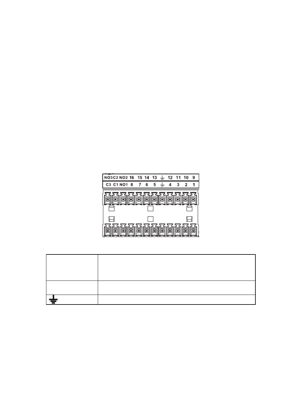
The following interface is based on the 8-channel advanced 1080P (V2) mini 1U Series. See Figure 3-1.
Figure 3-1
1,2,3,4,5,
6,7,8,9,10,
11,12,13,14,
15,16
ALARM 1 to ALARM 16. The alarm becomes active in low voltage.
NO1 C1,NO2 C2,
NO3 C3,
Three normal open groups (on/off signal)
Earth cable.
3.7.2 Alarm Input Port
Please refer to the following sheet for more informatio n.
Grounding alarm inputs. Normal open or Normal close type)
Please parallel connect COM end and GND end of the alarm detector ( Provide external power to the
alarm detector).
Please parallel connect the Ground of the DVR and the ground of the alarm detector.
Please connect the NC port of the alarm sensor to the DVR alarm input(ALARM)
Use the same ground with that of DVR if you use external power to the alarm device.