Powermax, Component replacement, Service manual 6-7 – Hypertherm Powermax45 Service Manual User Manual
Page 111
component replacement
powermax
45
Service Manual
6-7
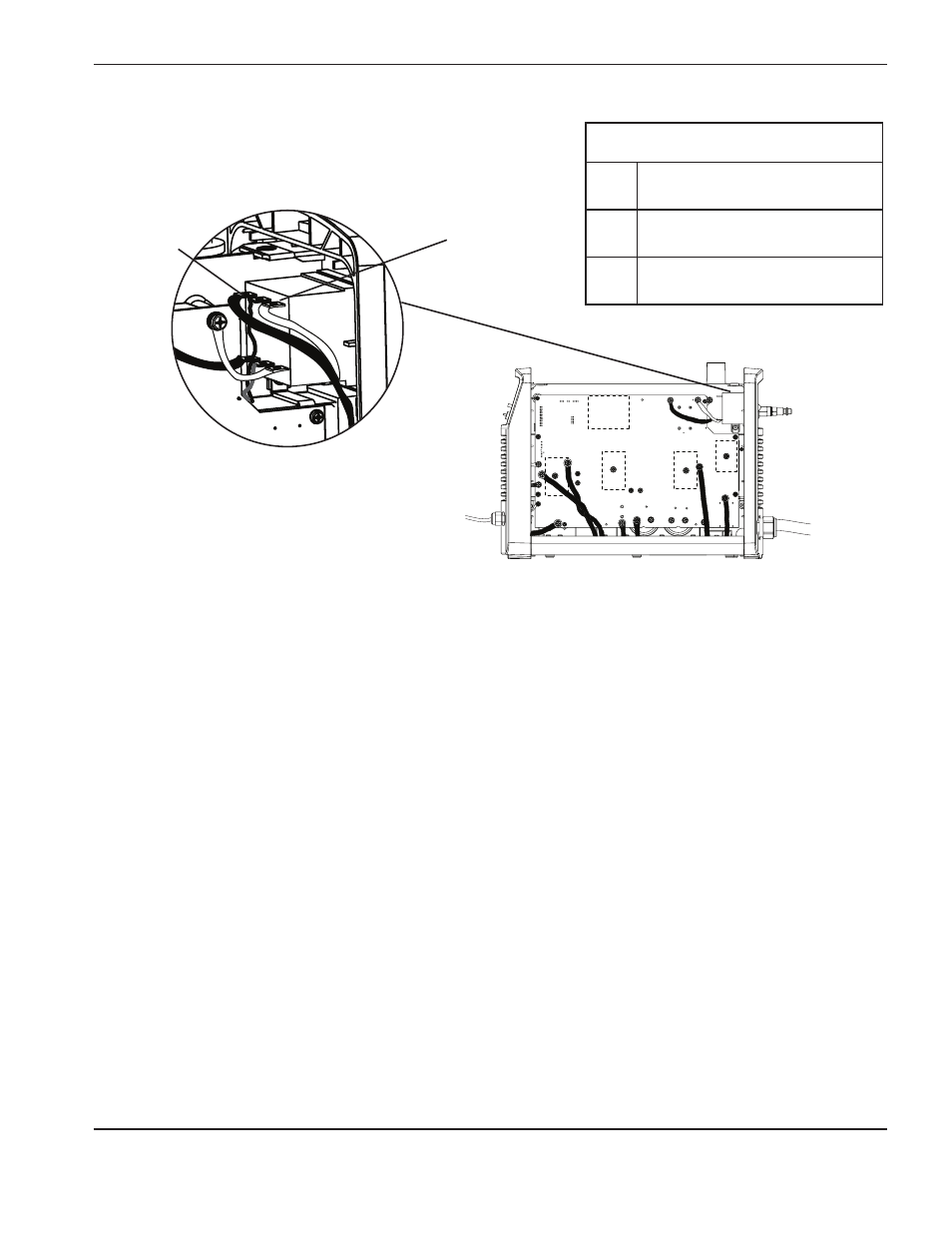
6. On the outside of the power supply, loosen the power cord’s strain relief retention nut so that the wires move
freely.
7. From the inside of the power supply, pull the wires through the strain relief and the hole in the rear end panel to
remove the old power cord.
8. If you are replacing the old strain relief with the new strain relief contained in the kit:
a. Use an adjustable wrench to unscrew the strain relief nut on the inside of the power supply to remove the old
strain relief.
b. Slide the new strain relief through the hole in the rear end panel of the power supply.
c. Secure the strain relief on the inside of the power supply using the new strain relief nut. Hand tighten the nut
and then over-tighten slightly more.
9. From the inside of the power supply, route the wires of the new power cord through the strain relief in the rear end
panel. Do not remove the tubular ferrite bead from the power switch end of the brown and blue wires. (Because
the CE power cord includes the ferrite bead, you cannot route the power cord through the strain relief from the
outside of the power supply.)
10. Slide the strain relief retention nut over the wires of the new power cord and slide the retention nut forward toward
the power supply.
11. Screw the connector for the brown wire onto the pin on the upper left side of the power switch with a torque
setting of 23.0 kg cm (20 inch-pounds).
l
Brown wire (CE)
N
Blue wire (CE)
Single phase (Ce)
L
Brown
N
Blue
PE
Green/yellow
TP 19
W
-
+
-
+
TP 18
R
TP 17
B
192 VDC
192 VDC