Powermax – Hypertherm Powermax45 Service Manual User Manual
Page 93
TroubleshooTing and sysTem TesTs
powermax
45
Service Manual
5-17
Use the control board error and Reset leds to troubleshoot
The Error and Reset LEDs provide information to use when troubleshooting a system failure. If the LEDs on the front of
the power supply are flashing, look at the Error LED on the control board to determine where the fault may be. Count the
number of flashes and then look at the table below to determine the corrective action.
Reset led
When the control board’s Reset LED illuminates, the voltages on the power board may be incorrect. Perform the
following tests at J7 on 200–240 V CSA power supplies and 230 V CE power supplies or J8 on 400 V CE and 480 V
CSA power supplies (the pin numbers are the same for all power supplies) on the power board (see Test 2 – power
board voltage checks on page 5-19):
• Test pin 25 to ground for 3.3 VDC (±10%).
• Test pin 24 to ground for 5 VDC (±10%).
• Test pin 12 to ground for 2.2 VDC (±10%).
If the values you find are not within ±10% of the above values, detach the control board’s ribbon cable and perform
the tests again. If you find the correct values the second time, replace the control board. Otherwise, replace the power
board.
error led
The number of times the Error LED flashes indicates the problem detected. Each flash is a half-second long and each
series of flashes is separated by a 2-second pause. See System tests on page 5-18 for detailed test procedures.
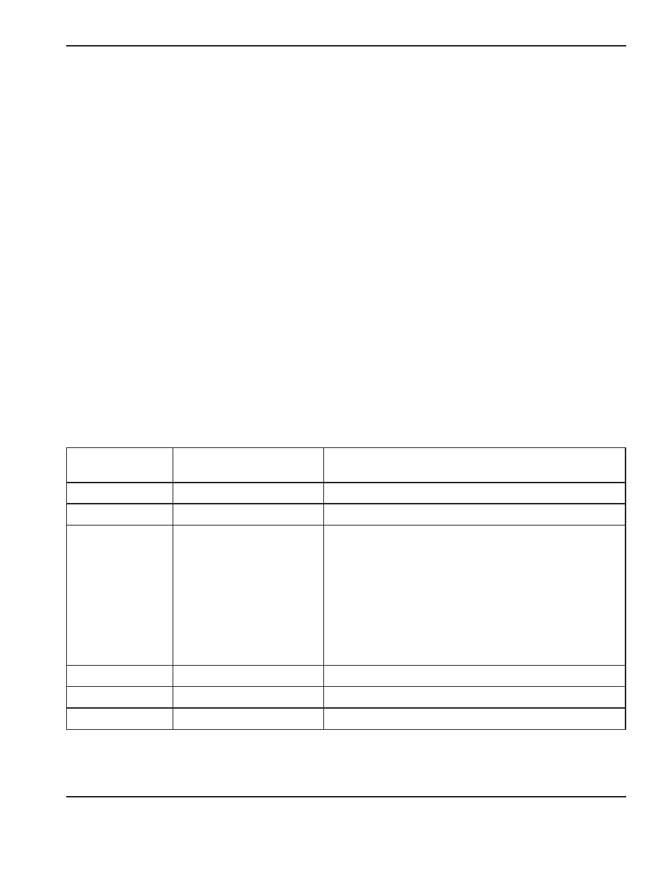
The following table shows the meaning associated with each set of flashes.
Number of error
led flashes
Problem indicated
Solution
1
Faulty control board
Replace the control board.
2
Faulty power board
Replace the power board.
3
Either a faulty power board
or a faulty control board
• Perform Test 3 – VBUS and voltage balance on page 5-20.
If any of the values are incorrect, replace the power board.
• Perform Test 2 – power board voltage checks on page
5-19. If any of the values for pins 5, 7, or 12 are incorrect,
remove the control board and test again. If the values are
correct, replace the control board.
• When performing test 2, if the values for pins 5, 7, and 12
are correct, but any other values are incorrect, replace the
power board.
4
Faulty gas solenoid valve
Replace the gas solenoid valve.
5
Faulty fan
Replace the fan.
6
Machine motion relay fault
Replace the power board.