Sierra Video G.R.I.P. V3.1.0 User Manual
Page 60
Sierra Video Systems
54
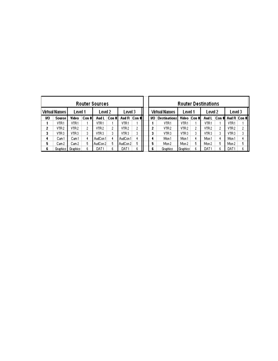
physical input connectors (e.g. input #4 connector) on three levels (VIDEO, AUD L, AUD
R) of a 3-level router, you could in fact place VTR1 video on VIDEO input connector #4,
put VTR1 audio left on AUD L connector #18, and put VTR1 audio right on AUD R
connector #44. You could still switch all three signals together using all-level takes, by
setting up the mapping table properly. This type of scrambled arrangement might at times
be necessary because some partially-stuffed routers may have holes in the video
connector numbering sequence but not in the audio connector numbering sequence. It
might also be a consequence of other factors, and is perfectly okay to do, though the
typical case, again, is to group signals from one machine together on the same input or
output connector number.
Example:
Decide which physical connectors to use for each source or destination signal group.
Normally this is a matter of simply assigning connectors in order, e.g. Input #1, Input #2,
etc. However, for partially-stuffed routers containing holes in the input or output
numbering, it is necessary to skip over the holes. Thus, a router with a potential for 96
inputs, but which actually has only 24 inputs, might use input connectors #1-#8, then skip
over #9-#32 and use #33-#40, skip #41-#64, use #65-#72, etc. Refer to your router user
manual for information about holes.
Choose the number of virtual sources and virtual destinations that the router is to have.
You can have up to 256 sources and 256 destinations in the Tahoe family of routers,
256x256 in the Yosemite family and even bigger in the Sequoia Family (contact the
factory for information regarding other product families). Normally you would choose an
option larger than your basic physical router size, to give you extra sources and
destinations to use. (You might choose to keep it under 100x100 if you desire to have 2-
digit input and output numbers rather than 3-digit ones, creating slightly shorter
crosspoint commands and status-back commands used by panels and control software,
but typically this wouldn’t be a concern).
Choose one or more input signals, each on a different level, that are to be switchable
together as a group using an all-level take, and assign a source number, beginning with
#1, to this group of input signals. Any levels may be left out of the source assignment,
that is, those levels may be unmapped for that source. Most of the time, all levels will be
included. In some cases, only some of them will be. For example, for a given group of
input signals, you might choose to use two source numbers, one that switches the video
input signal only, leaving the audio levels alone, and a second that switches the audio
input signals only, leaving the video level alone. Repeat this process until all input
signals, on all levels, have been assigned to at least one source number.
Give each source number a name. The same constraints in terms of number of
characters, allowable characters, and recommendations for prefixes and suffixes apply
here as for the choice of physical input and output names. When the source device is
different on different levels, a name must be chosen that applies to all levels. The name