Nat dns mapping configuration example, Network requirements, Configuration procedure – H3C Technologies H3C S12500 Series Switches User Manual
Page 126
112
[Device-Vlan-interface20] nat server protocol tcp global 202.38.1.1 21 inside 10.110.10.3
ftp
# Configure the internal web server 1.
[Device-Vlan-interface20] nat server protocol tcp global 202.38.1.1 80 inside 10.110.10.1
www
# Configure the internal web server 2.
[Device-Vlan-interface20] nat server protocol tcp global 202.38.1.1 8080 inside
10.110.10.2 www
# Configure the internal SMTP server.
[Device-Vlan-interface20] nat server protocol tcp global 202.38.1.1 smtp inside
10.110.10.4 smtp
[Device-Vlan-interface20] quit
NAT DNS mapping configuration example
Network requirements
A company provides web and FTP services to external users, and has its internal IP addresses on the
network segment 10.110.0.0/16. The IP addresses of the web and FTP servers are 10.110.10.1/16 and
10.110.10.2/16 respectively. The company has three public addresses 202.38.1.1/24 through
202.38.1.3/24. The DNS server is at 202.38.1.4/24. Configure NAT DNS mapping for the following
purposes:
•
The public IP address 202.38.1.2 is used to provide services to external users.
•
External users can use the public address or domain name of internal servers to access them.
•
Internal users can access the internal servers by using their domain names.
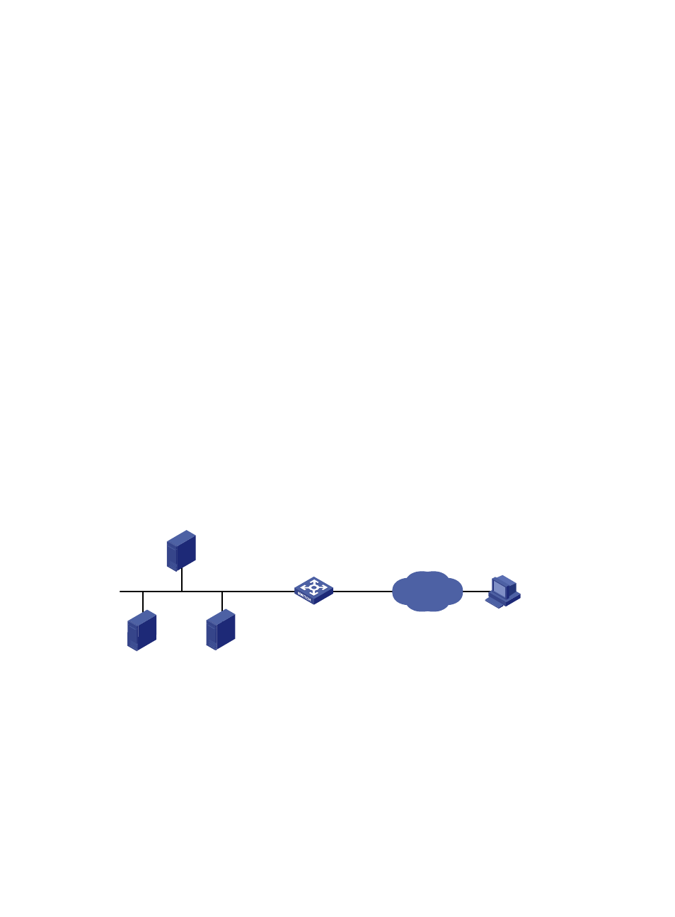
Figure 52 Network diagram
Configuration procedure
# Specify IP addresses for the interfaces, as shown in
. (Details not shown.)
# Enter the view of VLAN-interface 20.
<Device> system-view
[Device] interface vlan-interface 20
# Configure the internal web server.
[Device-Vlan-interface20] nat server protocol tcp global 202.38.1.2 inside 10.110.10.1
www
FTP server 2
10.110.10.2/16
FTP server 1
10.110.10.1/16
FTP server 3
10.110.10.3/16
Host
Internet
Vlan-int10
10.110.10.10/16
Vlan-int20
202.38.1.1/16
Device