Configuration procedure – H3C Technologies H3C S12500 Series Switches User Manual
Page 220
206
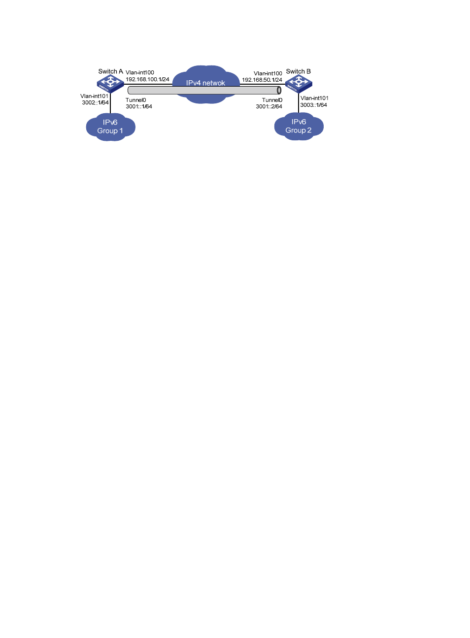
Figure 88 Network diagram
Configuration procedure
Make sure Switch A and Switch B have corresponding VLAN interfaces created and can reach each
other.
•
Configure Switch A:
# Enable IPv6.
<SwitchA> system-view
[SwitchA] ipv6
# Configure an IPv4 address for VLAN-interface 100.
[SwitchA] interface vlan-interface 100
[SwitchA-Vlan-interface100] ip address 192.168.100.1 255.255.255.0
[SwitchA-Vlan-interface100] quit
# Configure an IPv6 address for VLAN-interface 101.
[SwitchA] interface vlan-interface 101
[SwitchA-Vlan-interface101] ipv6 address 3002::1 64
[SwitchA-Vlan-interface101] quit
# Configure a manual IPv6 tunnel.
[SwitchA] interface tunnel 0
[SwitchA-Tunnel0] ipv6 address 3001::1/64
[SwitchA-Tunnel0] source vlan-interface 100
[SwitchA-Tunnel0] destination 192.168.50.1
[SwitchA-Tunnel0] tunnel-protocol ipv6-ipv4
[SwitchA-Tunnel0] quit
# Configure a static route to IPv6 Group 2 through tunnel 0 on Switch A.
[SwitchA] ipv6 route-static 3003:: 64 tunnel 0
•
Configure Switch B:
# Enable IPv6.
<SwitchB> system-view
[SwitchB] ipv6
# Configure an IPv4 address for VLAN-interface 100.
[SwitchB] interface vlan-interface 100
[SwitchB-Vlan-interface100] ip address 192.168.50.1 255.255.255.0
[SwitchB-Vlan-interface100] quit
# Configure an IPv6 address for VLAN-interface 101.
[SwitchB] interface vlan-interface 101
[SwitchB-Vlan-interface101] ipv6 address 3003::1 64
[SwitchB-Vlan-interface101] quit