Configuration procedure – H3C Technologies H3C S12500 Series Switches User Manual
Page 81
67
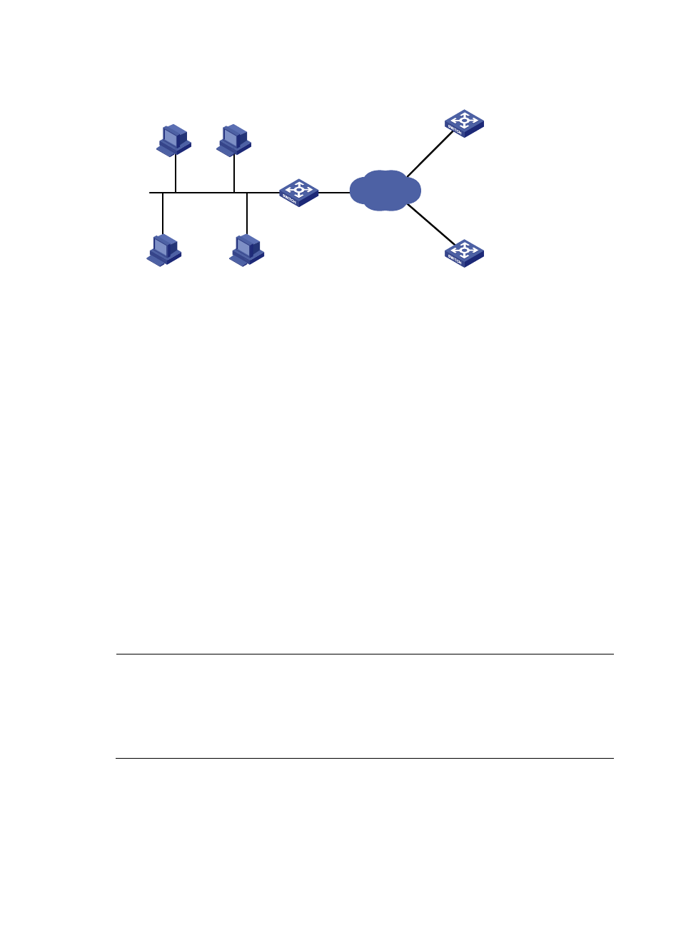
Figure 32 Network diagram
Configuration procedure
# Specify IP addresses for the interfaces. (Details not shown.)
# Enable DHCP.
<SwitchA> system-view
[SwitchA] dhcp enable
# Add DHCP servers 10.1.1.1 and 10.2.1.1 into DHCP server group 1.
[SwitchA] dhcp relay server-group 1 ip 10.1.1.1
[SwitchA] dhcp relay server-group 1 ip 10.2.1.1
# Enable the DHCP relay agent on VLAN-interface 1.
[SwitchA] interface vlan-interface 1
[SwitchA-Vlan-interface1] dhcp select relay
# Correlate VLAN-interface 1 to DHCP server group 1.
[SwitchA-Vlan-interface1] dhcp relay server-select 1
After the preceding configuration is complete, DHCP clients can obtain IP addresses and other network
parameters through the DHCP relay agent from the DHCP servers. You can use the display dhcp relay
statistics command to view statistics of DHCP packets forwarded by DHCP relay agents. After you enable
address check of the DHCP relay agents with the dhcp relay address-check enable command, use the
display dhcp relay security command to view bindings of DHCP relay agents.
NOTE:
•
Because the DHCP relay agent and servers are on different subnets, you must configure a static route or
dynamic routing protocol to make them reachable to each other.
•
Configurations on the DHCP servers are also required to guarantee the client-server communication
through the DHCP relay agent. For DHCP server configuration information, see "
DHCP client
Switch B
DHCP server
Switch A
DHCP relay agent
DHCP client
DHCP client
DHCP client
Vlan-int1
10.10.1.1/24
Vlan-int2
10.1.1.1/24
Switch C
DHCP server
Vlan-int3
10.2.1.1/24
IP network