Configuration example, Network requirements, Configuration procedure – H3C Technologies H3C S12500 Series Switches User Manual
Page 136
122
Step Command
Remarks
1.
Enter system view.
system-view
N/A
2.
Enter VLAN interface view.
interface interface-type
interface-number
N/A
3.
Enable forwarding of
directed broadcasts to a
directly connected network
on the interface.
ip forward-broadcast
By default, the switch is disabled from
forwarding directed broadcasts to a
directly connected network but it can
receive directed broadcasts destined for
the directly connected network.
Configuration example
Network requirements
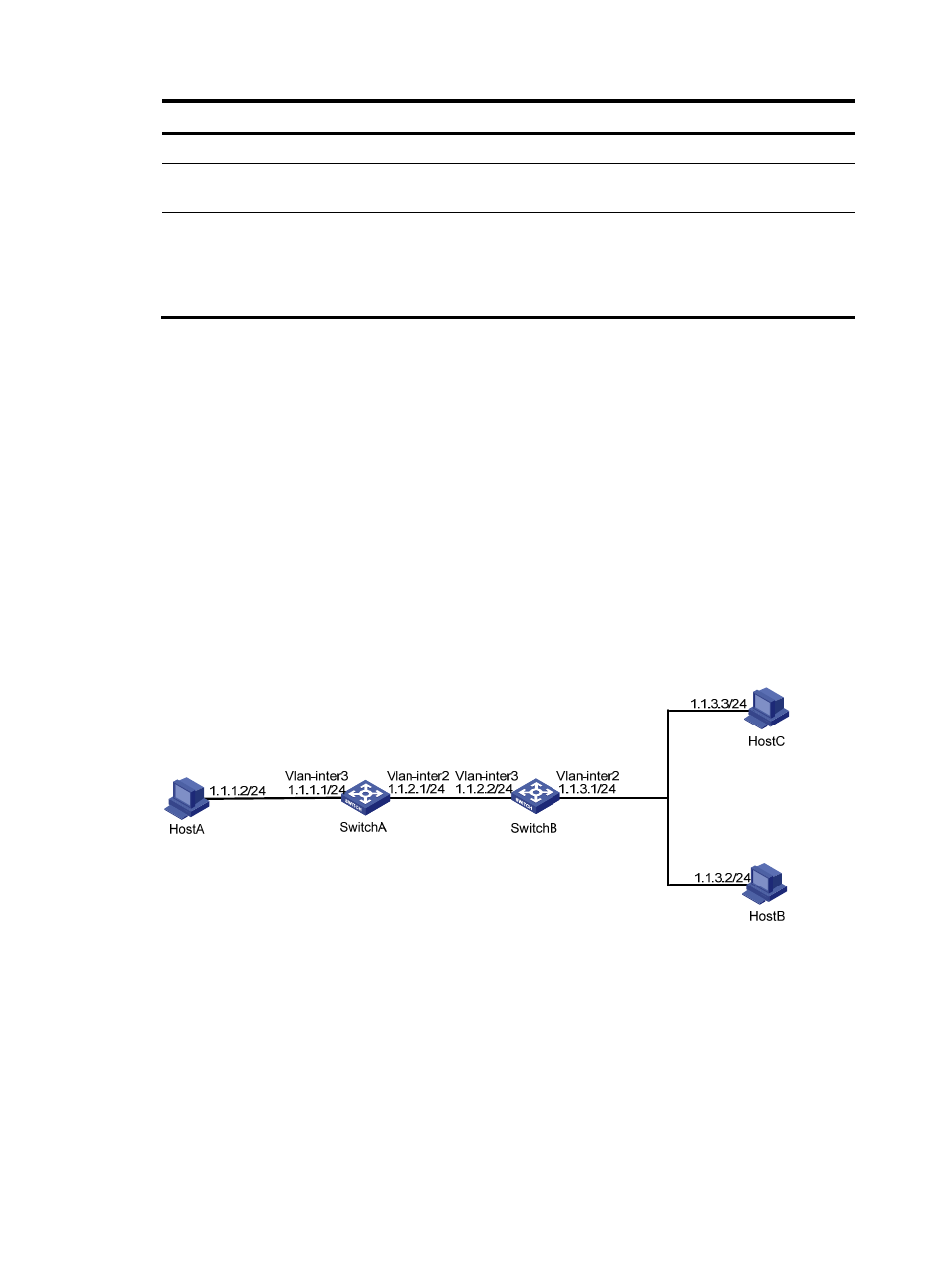
As shown in
, the interface of Host A and VLAN-interface 3 of Switch A are located on network
segment 1.1.1.0/24. VLAN-interface 2 of Switch A and VLAN-interface 3 of Switch B are located on
network segment 1.1.2.0/24. VLAN-interface 2 of Switch B, Host B, and Host C are located on network
segment 1.1.3.0/24. The default gateway of Host A is VLAN-interface 3 (IP address 1.1.1.1/24) of Switch
A. The default gateway of Host B and Host C is VLAN-interface 2 (IP address 1.1.3.1/24) of Switch B.
Configure static routes on Switch A and Switch B for reachability between Host A and Host B, and Host
A and Host C, respectively.
Enable forwarding of directed broadcasts on Switch A and Switch B so that Host C and Host B can
receive directed broadcasts from Host A.
Figure 55 Network diagram
Configuration procedure
1.
Configure Switch A:
# Configure a static route on Switch A.
<SwitchA> system-view
[SwitchA] ip route-static 1.1.3.0 255.255.255.0 1.1.2.2
# Configure IP addresses for VLAN-interface 3 and VLAN-interface 2.
[SwitchA] interface vlan-interface 3
[SwitchA-Vlan-interface3] ip address 1.1.1.1 24
[SwitchA-Vlan-interface3] quit